- Radar Systems Tutorial
- Radar Systems - Home
- Radar Systems - Overview
- Radar Systems - Range Equation
- Performance Factors
- Radar Systems - Types of Radars
- Radar Systems - Pulse Radar
- Radar Systems - Doppler Effect
- Radar Systems - CW Radar
- Radar Systems - FMCW Radar
- Radar Systems - MTI Radar
- Delay Line Cancellers
- Radar Systems - Tracking Radar
- Antenna Parameters
- Radar Systems - Radar Antennas
- Matched Filter Receiver
- Radar Systems - Radar Displays
- Radar Systems - Duplexers
- Phased Array Antennas
- Radar Systems Useful Resources
- Radar Systems - Quick Guide
- Radar Systems - Useful Resources
- Radar Systems - Discussion
Radar Systems - Tracking Radar
The Radar, which is used to track the path of one or more targets is known as Tracking Radar. In general, it performs the following functions before it starts the tracking activity.
- Target detection
- Range of the target
- Finding elevation and azimuth angles
- Finding Doppler frequency shift
So, Tracking Radar tracks the target by tracking one of the three parameters — range, angle, Doppler frequency shift. Most of the Tracking Radars use the principle of tracking in angle. Now, let us discuss what angular tracking is.
Angular Tracking
The pencil beams of Radar Antenna perform tracking in angle. The axis of Radar Antenna is considered as the reference direction. If the direction of the target and reference direction is not same, then there will be angular error, which is nothing but the difference between the two directions.
If the angular error signal is applied to a servo control system, then it will move the axis of the Radar Antenna towards the direction of target. Both the axis of Radar Antenna and the direction of target will coincide when the angular error is zero. There exists a feedback mechanism in the Tracking Radar, which works until the angular error becomes zero.
Following are the two techniques, which are used in angular tracking.
- Sequential Lobing
- Conical Scanning
Now, let us discuss about these two techniques one by one.
Sequential Lobing
If the Antenna beams are switched between two patterns alternately for tracking the target, then it is called sequential lobing. It is also called sequential switching and lobe switching. This technique is used to find the angular error in one coordinate. It gives the details of both magnitude and direction of angular error.
Following figure shows an example of sequential lobing in polar coordinates.
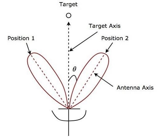
As shown in the figure, Antenna beams switch between Position 1 and Position 2 alternately. Angular error θ is indicated in the above figure. Sequential lobing gives the position of the target with high accuracy. This is the main advantage of sequential lobing.
Conical Scanning
If the Antenna beam continuously rotates for tracking a target, then it is called conical scanning. Conical scan modulation is used to find the position of the target. Following figure shows an example of conical scanning.
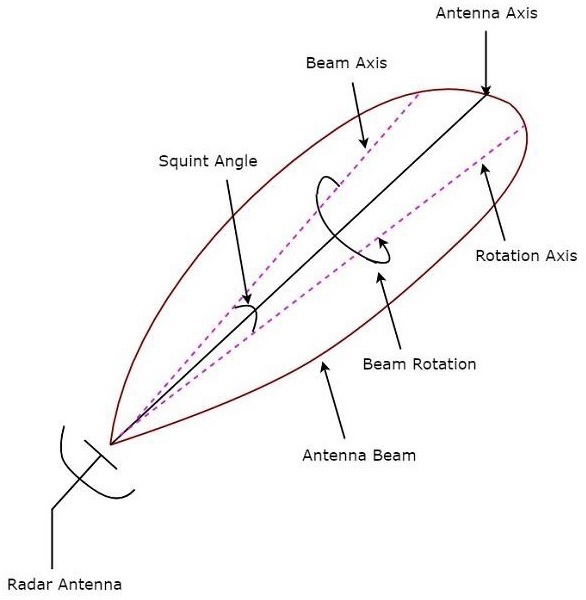
Squint angle is the angle between beam axis and rotation axis and it is shown in the above figure. The echo signal obtained from the target gets modulated at a frequency equal to the frequency at which the Antenna beam rotates.
The angle between the direction of the target and the rotation axis determines the amplitude of the modulated signal. So, the conical scan modulation has to be extracted from the echo signal and then it is to be applied to servo control system, which moves the Antenna beam axis towards the direction of the target.