- Computer Organization Tutorial
- CO - Home
- CO - Overview
- CO - Digital Number System
- CO - Number System Conversion
- CO - Binary Codes
- CO - Codes Conversion
- CO - Complement Arithmetic
- CO - Binary Arithmetic
- CO - Octal Arithmetic
- CO - Hexadecimal Arithmetic
- CO - Boolean Algebra
- CO - Logic Gates
- CO - Combinational Circuits
- CO - Sequential Circuits
- CO - Digital Registers
- CO - Digital Counters
- CO - Memory Devices
- CO - CPU Architecture
- Computer Organization Resources
- CO - Quick Guide
- CO - Useful Resources
- CO - Discussion
Logic Gates
Logic gates are the basic building blocks of any digital system. It is an electronic circuit having one or more than one input and only one output. The relationship between the input and the output is based on a certain logic. Based on this, logic gates are named as AND gate, OR gate, NOT gate etc.
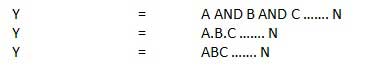
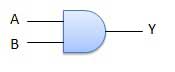
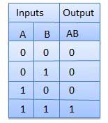
AND Gate
A circuit which performs an AND operation is shown in figure. It has n input (n >= 2) and one output.
Logic diagram
Truth Table
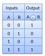
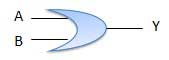
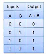
OR Gate
A circuit which performs an OR operation is shown in figure. It has n input (n >= 2) and one output.
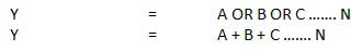
Logic diagram
Truth Table
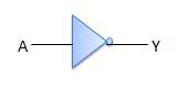
NOT Gate
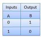
NOT gate is also known as Inverter. It has one input A and one output Y.
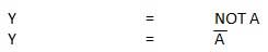
Logic diagram
Truth Table
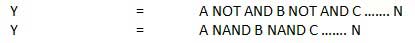
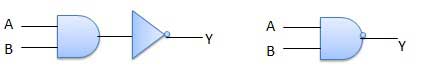
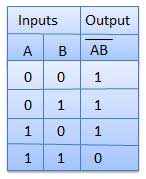
NAND Gate
A NOT-AND operation is known as NAND operation. It has n input (n >= 2) and one output.
Logic diagram
Truth Table
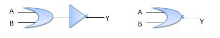
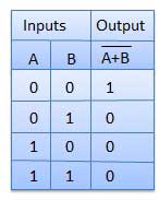
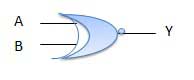
NOR Gate
A NOT-OR operation is known as NOR operation. It has n input (n >= 2) and one output.
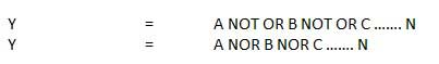
Logic diagram
Truth Table
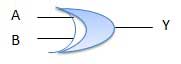
XOR Gate
XOR or Ex-OR gate is a special type of gate. It can be used in the half adder, full adder and subtractor. The exclusive-OR gate is abbreviated as EX-OR gate or sometime as X-OR gate. It has n input (n >= 2) and one output.
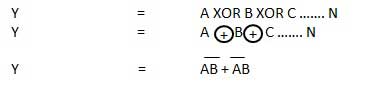
Logic diagram
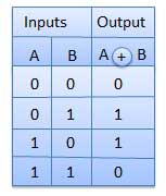
Truth Table
XNOR Gate
XNOR gate is a special type of gate. It can be used in the half adder, full adder and subtractor. The exclusive-NOR gate is abbreviated as EX-NOR gate or sometime as X-NOR gate. It has n input (n >= 2) and one output.
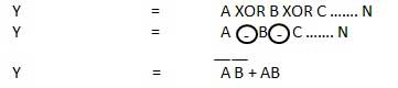
Logic diagram
Truth Table