
Article Categories
- All Categories
-
 Data Structure
-
 Networking
-
 RDBMS
RDBMS
-
 Operating System
-
 Java
Java
-
 MS Excel
-
 iOS
iOS
-
 HTML
HTML
-
 CSS
CSS
-
 Android
-
 Python
-
 C Programming
-
 C++
C++
-
 C#
C#
-
 MongoDB
-
 MySQL
MySQL
-
 Javascript
-
 PHP
PHP
What is General Register Organization?
A set of flip-flops forms a register. A register is a unique high-speed storage area in the CPU. They include combinational circuits that implement data processing. The information is always defined in a register before processing. The registers speed up the implementation of programs.
Registers implement two important functions in the CPU operation are as follows −
- It can support a temporary storage location for data. This supports the directly implementing programs to have fast access to the data if required.
- It can save the status of the CPU and data about the directly implementing program.
Example − Address of the next program instruction, signals get from the external devices and error messages, and including different data is saved in the registers.
If a CPU includes some registers, therefore a common bus can link these registers. A general organization of seven CPU registers is displayed in the figure.
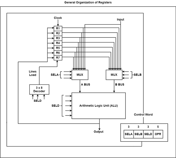
The CPU bus system is managed by the control unit. The control unit explicit the data flow through the ALU by choosing the function of the ALU and components of the system.
Consider R1 ← R2 + R3, the following are the functions implemented within the CPU −
MUX A Selector (SELA) − It can place R2 into bus A.
MUX B Selector (SELB) − It can place R3 into bus B.
ALU Operation Selector (OPR) − It can select the arithmetic addition (ADD).
Decoder Destination Selector (SELD) − It can transfers the result into R1.
The multiplexers of 3-state gates are performed with the buses. The state of 14 binary selection inputs determines the control word. The 14-bit control word defines a micro-operation.
The encoding of register selection fields is specified in the table.
Encoding of Register Selection Field
| Binary Code | SELA | SELB | SELD |
|---|---|---|---|
| 000 | Input | Input | None |
| 001 | R1 | R1 | R1 |
| 010 | R2 | R2 | R2 |
| 011 | R3 | R3 | R3 |
| 100 | R4 | R4 | R4 |
| 101 | R5 | R5 | R5 |
| 110 | R6 | R6 | R6 |
| 111 | R7 | R7 | R7 |
There are several micro-operations are implemented by the ALU. Few of the operations implemented by the ALU are displayed in the table.
Encoding of ALU Operations
| OPR Select | Operation | Symbol |
|---|---|---|
| 00000 | Transfer A | TSFA |
| 00001 | Increment A | INCA |
| 00010 | Add A + B | ADD |
| 00101 | Subtract A - B | SUB |
| 00110 | Decrement A | DECA |
| 01000 | ADD A and B | AND |
| 01010 | OR A and B | OR |
| 01100 | XOR A and B | XOR |
| 01110 | Complement A | COMA |
| 10000 | Shift right A | SHRA |
| 11000 | Shift left A | SHLA |
There are some ALU micro-operations are shown in the table.
ALU Micro-Operations
| Micro-operation | SELA | SELB | SELD | OPR | Control Word | |||
| R1 ← R2 – R3 | R2 | R3 | R1 | SUB | 010 | 011 | 001 | 00101 |
| R4 ← R4 ∨ R5 | R4 | R5 | R4 | OR | 100 | 101 | 100 | 01010 |
| R6 ← R6 + R1 | - | R6 | R1 | INCA | 110 | 000 | 110 | 00001 |
| R7 ← R1 | R1 | - | R7 | TSFA | 001 | 000 | 111 | 00000 |
| Output ← R2 | R2 | – | None | TSFA | 010 | 000 | 000 | 00000 |
| Output ← Input | Input | - | None | TSFA | 000 | 000 | 000 | 00000 |
| R4 ← shl R4 | R4 | - | R4 | SHLA | 100 | 000 | 100 | 11000 |
| R5 ← 0 | R5 | R5 | R5 | XOR | 101 | 101 | 101 | 01100 |

91K+ Views
