
Article Categories
- All Categories
-
 Data Structure
-
 Networking
-
 RDBMS
RDBMS
-
 Operating System
-
 Java
Java
-
 MS Excel
-
 iOS
iOS
-
 HTML
HTML
-
 CSS
CSS
-
 Android
-
 Python
-
 C Programming
-
 C++
C++
-
 C#
C#
-
 MongoDB
-
 MySQL
MySQL
-
 Javascript
-
 PHP
PHP
-
 Economics & Finance
What is Register Transfer?
Registers define the storage area that influences the data and instructions. It can send data and instructions from one register to another register, memory to register, and memory to memory, the register transfer approach is used. This register is used in the transmission of data and instructions between memory and processors to implement the particular tasks.
The data transfer from one register to another is named in representative design using a replacement operator. The statement is
R2←R1
It indicates a transfer of the content of register R1 into register R2. It labelled a replacement of the content of R2 by the content of R1. The content of the source register R1 does not shift after the transfer.
A statement that specifies a register transfer involves that circuits are accessible from the outputs of the source register to the inputs of the destination register and that the destination register has a corresponding load efficiency.
![]()
We need the transfer to appear only under a fixed control condition. This can be displayed using an if-then statement.
If (P = 1) then (R2 ← R1)
where P is a control signal created in the control area. A control function is a Boolean variable that is similar to 1 or 0. The control function is contained in the statement as follows −
P: R2 ← R1
The control condition is terminated with a colon. It represents the specification that the transfer operation is implemented by the hardware only if P = 1. Each statement written in a register transfer notation indicates a hardware structure for executing the transfer.
The diagram demonstrates the block diagram that shows the transfer from R1 to R2. The n outputs of register R1 are linked to the n inputs of register R2. The letter n can denote any number of bits for the register. It will be restored by an actual number when the duration of the register is established.
Register R2 has a load input that is activated by the control variable P. It is considered that the control variable is synchronized with the equivalent clock like the one used to the register.
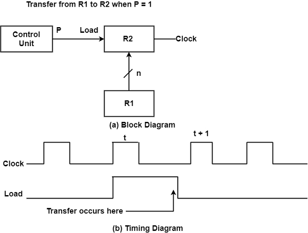
As displayed in the timing diagram, P is activated in the control area by the increasing edge of a clock pulse at time t. The next positive transition of the clock at time t + 1 discovers the load input active and the data inputs of R2 are then loaded into the register in parallel. P can go back to 0 at time t + 1. The transfer will appear with each clock pulse transition while P stays active.
The clock is not contained as a variable in the register transfer statements. It is considered that all transfers appear during a clock edge transition. The control condition including P becomes active only after time t, the actual transfer does not appear until the register is triggered by the next positive transition of the clock at time t + 1.

21K+ Views
