- Home
- Basics of Integrated Circuits Applications
- Basics Operational Amplifier
- Op-Amp applications
- Arithmetic Circuits
- Differentiator & Integrator
- Converters Of Electrical Quantities
- Comparators
- Log & Anti-Log Amplifiers
- Rectifiers
- Clippers
- Clampers
- Active Filters
- Sinusoidal Oscillators
- Waveform Generators
- 555 Timer
- Phase Locked Loop Ic
- Voltage Regulators
- Data Converters
- Digital to Analog Converters
- DAC Example Problem
- Direct Type ADCs
- Indirect Type ADC
Indirect Type ADC
In the previous chapter, we discussed about what an ADC is and the examples of a Direct type ADC. This chapter discusses about the Indirect type ADC.
If an ADC performs the analog to digital conversion by an indirect method, then it is called an Indirect type ADC. In general, first it converts the analog input into a linear function of time (or frequency) and then it will produce the digital (binary) output.
Dual slope ADC is the best example of an Indirect type ADC. This chapter discusses about it in detail.
Dual Slope ADC
As the name suggests, a dual slope ADC produces an equivalent digital output for a corresponding analog input by using two (dual) slope technique.
The block diagram of a dual slope ADC is shown in the following figure −
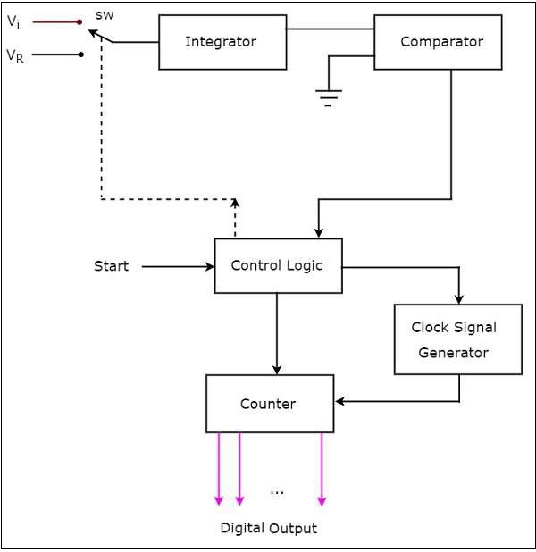
The dual slope ADC mainly consists of 5 blocks: Integrator, Comparator, Clock signal generator, Control logic and Counter.
The working of a dual slope ADC is as follows −
The control logic resets the counter and enables the clock signal generator in order to send the clock pulses to the counter, when it is received the start commanding signal.
Control logic pushes the switch sw to connect to the external analog input voltage $V_{i}$, when it is received the start commanding signal. This input voltage is applied to an integrator.
The output of the integrator is connected to one of the two inputs of the comparator and the other input of comparator is connected to ground.
Comparator compares the output of the integrator with zero volts (ground) and produces an output, which is applied to the control logic.
The counter gets incremented by one for every clock pulse and its value will be in binary (digital) format. It produces an overflow signal to the control logic, when it is incremented after reaching the maximum count value. At this instant, all the bits of counter will be having zeros only.
Now, the control logic pushes the switch sw to connect to the negative reference voltage $-V_{ref}$. This negative reference voltage is applied to an integrator. It removes the charge stored in the capacitor until it becomes zero.
At this instant, both the inputs of a comparator are having zero volts. So, comparator sends a signal to the control logic. Now, the control logic disables the clock signal generator and retains (holds) the counter value. The counter value is proportional to the external analog input voltage.
At this instant, the output of the counter will be displayed as the digital output. It is almost equivalent to the corresponding external analog input value $V_{i}$.
The dual slope ADC is used in the applications, where accuracy is more important while converting analog input into its equivalent digital (binary) data.
