- Home
- Basics of Integrated Circuits Applications
- Basics Operational Amplifier
- Op-Amp applications
- Arithmetic Circuits
- Differentiator & Integrator
- Converters Of Electrical Quantities
- Comparators
- Log & Anti-Log Amplifiers
- Rectifiers
- Clippers
- Clampers
- Active Filters
- Sinusoidal Oscillators
- Waveform Generators
- 555 Timer
- Phase Locked Loop Ic
- Voltage Regulators
- Data Converters
- Digital to Analog Converters
- DAC Example Problem
- Direct Type ADCs
- Indirect Type ADC
DAC Example Problem
In the previous chapter, we discussed the two types of DACs. This chapter discusses an example problem based on R-2R ladder DAC.
Example
Let us find the value of analog output voltage of R-2R Ladder DAC for a binary input, $b_{2}b_{1}b_{0}$ = 100.
Circuit Diagram and its Simplification
The circuit diagram of a 3-bit R-2R Ladder DAC when binary input, $b_{2}b_{1}b_{0}$ = 100 applied to it is shown in the following figure −
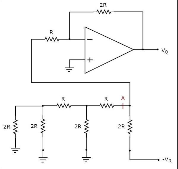
In the above circuit, there exists series and parallel combinations of resistors to the left of point A with respect to ground. So, we can replace that entire resistor network with a single resistor having resistance of $2R\Omega$.
The simplified circuit diagram is shown in the following figure −
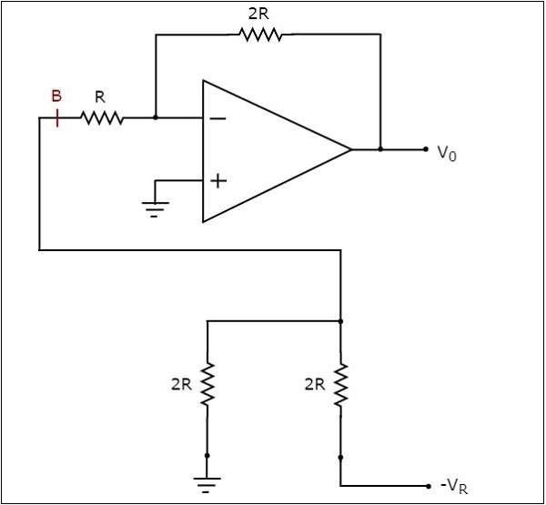
We can replace the part of the network that is connected to the left of point B with respect to ground by using a Thevenins equivalent circuit. The modified circuit diagram is shown in the following figure −
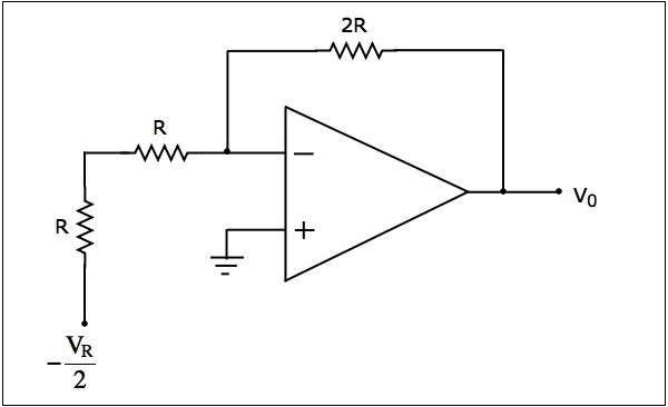
In the above circuit, there exist a series combination of two resistors. Replace this combination with a single resistor. The final circuit diagram after simplification is shown in the following figure −
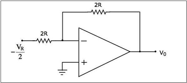
Now, the above circuit diagram looks like an inverting amplifier. It is having an input voltage of $-\frac{V_{R}}{2}$ volts, input resistance of $2R\Omega$ and feedback resistance of $2R\Omega$.
The output voltage of the circuit shown above will be −
$$V_{0}=-\frac{2R}{2R}\left(-\frac{V_{R}}{2}\right)$$
$$V_{0}=\frac{V_{R}}{2}$$
Therefore, the output voltage of 3-bit R-2R Ladder DAC is $\frac{V_{R}}{2}$ volts for a binary input, $b_{2}b_{1}b_{0}$ = 100.
