- Home
- Basics of Integrated Circuits Applications
- Basics Operational Amplifier
- Op-Amp applications
- Arithmetic Circuits
- Differentiator & Integrator
- Converters Of Electrical Quantities
- Comparators
- Log & Anti-Log Amplifiers
- Rectifiers
- Clippers
- Clampers
- Active Filters
- Sinusoidal Oscillators
- Waveform Generators
- 555 Timer
- Phase Locked Loop Ic
- Voltage Regulators
- Data Converters
- Digital to Analog Converters
- DAC Example Problem
- Direct Type ADCs
- Indirect Type ADC
Clippers
Wave shaping circuits are the electronic circuits, which produce the desired shape at the output from the applied input wave form. These circuits perform two functions −
- Attenuate the applied wave
- Alter the dc level of the applied wave.
There are two types of wave shaping circuits: Clippers and Clampers. In this chapter, you will learn in detail about clippers.
Op-amp based Clippers
A clipper is an electronic circuit that produces an output by removing a part of the input above or below a reference value. That means, the output of a clipper will be same as that of the input for other than the clipped part. Due to this, the peak to peak amplitude of the output of a clipper will be always less than that of the input.
The main advantage of clippers is that they eliminate the unwanted noise present in the amplitude of an ac signal.
Clippers can be classified into the following two types based on the clipping portion of the input.
- Positive Clipper
- Negative Clipper
These are discussed in detail as given below −
Positive Clipper
A positive clipper is a clipper that clips only the positive portion(s) of the input signal.
The circuit diagramof positive clipper is shown in the following figure −
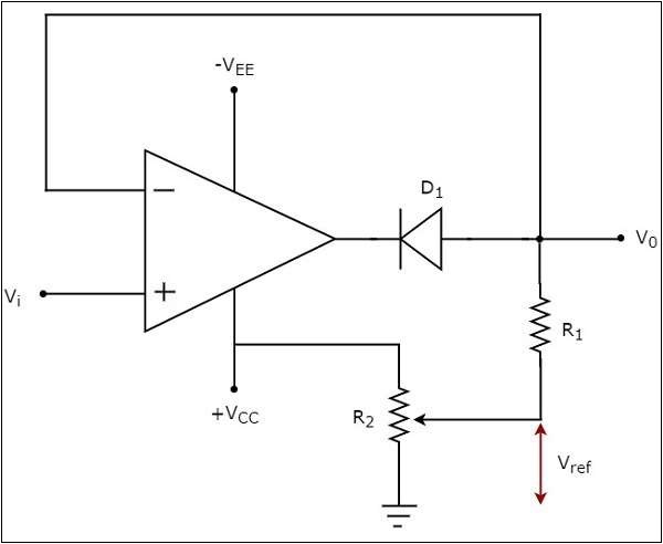
In the circuit shown above, a sinusoidal voltage signal $V_{t}$ is applied to the non-inverting terminal of the op-amp. The value of the reference voltage $V_{ref}$ can be chosen by varying the resistor $R_{2}$.
The operation of the circuit shown above is explained below −
If the value of the input voltage $V_i$ is less than the value of the reference voltage $V_{ref}$, then the diode D1 conducts. Then, the circuit given above behaves as a voltage follower. Therefore, the output voltage $V_{0}$ of the above circuit will be same as that of the input voltage $V_{i}$, for $V_{i}$ < $V_{ref}$.
If the value of the input voltage $V_{i}$ is greater than the value of reference voltage $V_{ref}$, then the diode D1 will be off. Now, the op-amp operates in an open loop since the feedback path was open. Therefore, the output voltage $V_{0}$ of the above circuit will be equal to the value of the reference voltage $V_{ref}$, for $V_{i}$ > $V_{ref}$.
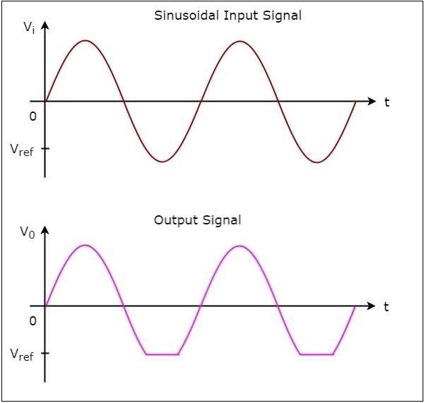
The input wave form and the corresponding output wave form of a positive clipper for a positive reference voltage $V_{ref}$, are shown in the following figure −
Negative Clipper
A negative clipper is a clipper that clips only the negative portion(s) of the input signal. You can obtain the circuit of the negative clipper just by reversing the diode and taking the reverse polarity of the reference voltage, in the circuit that you have seen for a positive clipper.
The circuit diagram of a negative clipper is shown in the following figure −
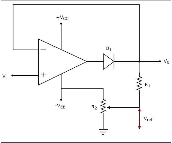
In the above circuit, a sinusoidal voltage signal $V_{i}$ is applied to the non-inverting terminal of the op-amp. The value of the reference voltage $V_{ref}$ can be chosen by varying the resistor $R_{2}$.
The operation of a negative clipper circuit is explained below −
If the value of the input voltage $V_{t}$ is greater than the value of reference voltage $V_{ref}$, then the diode D1 conducts. Then, the above circuit behaves as a voltage follower. Therefore, the output voltage $V_{0}$ of the above circuit will be same as that of the input voltage $V_{i}$ for $V_{i}$> $V_{ref}$.
If the value of the input voltage $V_{i}$ is less than the value of reference voltage , then the diode D1 will be off. Now, the op-amp operates in an open loop since the feedback path is open. Therefore, the output voltage $V_{0}$ of the above circuit will be equal to the value of reference voltage ,$V_{ref}$ for $V_{i}$ < $V_{ref}$.
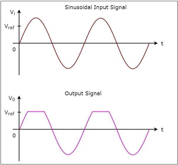
The input wave form and the corresponding output wave form of a negative clipper, for a negative reference voltage $V_{ref}$, are shown in the following figure −