- Home
- Basics of Integrated Circuits Applications
- Basics Operational Amplifier
- Op-Amp applications
- Arithmetic Circuits
- Differentiator & Integrator
- Converters Of Electrical Quantities
- Comparators
- Log & Anti-Log Amplifiers
- Rectifiers
- Clippers
- Clampers
- Active Filters
- Sinusoidal Oscillators
- Waveform Generators
- 555 Timer
- Phase Locked Loop Ic
- Voltage Regulators
- Data Converters
- Digital to Analog Converters
- DAC Example Problem
- Direct Type ADCs
- Indirect Type ADC
Converters Of Electrical Quantities
Voltage and current are the basic electrical quantities. They can be converted into one another depending on the requirement. Voltage to Current Converter and Current to Voltage Converter are the two circuits that help in such conversion. These are also linear applications of op-amps. This chapter discusses them in detail.
Voltage to Current Converter
A voltage to current converter or V to I converter, is an electronic circuit that takes current as the input and produces voltage as the output. This section discusses about the op-amp based voltage to current converter.
An op-amp based voltage to current converter produces an output current when a voltage is applied to its non-inverting terminal. The circuit diagram of an op-amp based voltage to current converter is shown in the following figure.
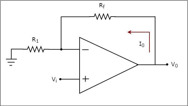
In the circuit shown above, an input voltage $V_{i}$ is applied at the non-inverting input terminal of the op-amp. According to the virtual short concept, the voltage at the inverting input terminal of an op-amp will be equal to the voltage at its non-inverting input terminal . So, the voltage at the inverting input terminal of the op-amp will be $V_{i}$.
The nodal equation at the inverting input terminal's node is −
$$\frac{V_i}{R_1}-I_{0}=0$$
$$=>I_{0}=\frac{V_t}{R_1}$$
Thus, the output current $I_{0}$ of a voltage to current converter is the ratio of its input voltage $V_{i}$ and resistance $R_{1}$.
We can re-write the above equation as −
$$\frac{I_0}{V_i}=\frac{1}{R_1}$$
The above equation represents the ratio of the output current $I_{0}$ and the input voltage $V_{i}$ & it is equal to the reciprocal of resistance $R_{1}$ The ratio of the output current $I_{0}$ and the input voltage $V_{i}$ is called as Transconductance.
We know that the ratio of the output and the input of a circuit is called as gain. So, the gain of an voltage to current converter is the Transconductance and it is equal to the reciprocal of resistance $R_{1}$.
Current to Voltage Converter
A current to voltage converter or I to V converter is an electronic circuit that takes current as the input and produces voltage as the output. This section discusses about the op-amp based current to voltage converter.
An op-amp based current to voltage converter produces an output voltage when current is applied to its inverting terminal. The circuit diagram of an op-amp based current to voltage converter is shown in the following figure.
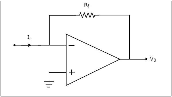
In the circuit shown above, the non-inverting input terminal of the op-amp is connected to ground. That means zero volts is applied at its non-inverting input terminal.
According to the virtual short concept, the voltage at the inverting input terminal of an op-amp will be equal to the voltage at its non-inverting input terminal. So, the voltage at the inverting input terminal of the op-amp will be zero volts.
The nodal equation at the inverting terminal's node is −
$$-I_{i}+\frac{0-V_0}{R_f}=0$$
$$-I_{i}=\frac{V_0}{R_f}$$
$$V_{0}=-R_{t}I_{i}$$
Thus, the output voltage, $V_{0}$ of current to voltage converter is the (negative) product of the feedback resistance, $R_{f}$ and the input current, $I_{t}$. Observe that the output voltage, $V_{0}$ is having a negative sign, which indicates that there exists a 1800 phase difference between the input current and output voltage.
We can re-write the above equation as −
$$\frac{V_0}{I_i}=-R_{f}$$
The above equation represents the ratio of the output voltage $V_{0}$ and the input current $I_{i}$, and it is equal to the negative of feedback resistance, $R_{f}$. The ratio of output voltage $V_{0}$ and input current $I_{i}$ is called as Transresistance.
We know that the ratio of output and input of a circuit is called as gain. So, the gain of a current to voltage converter is its trans resistance and it is equal to the (negative) feedback resistance $R_{f}$ .
