- Home
- Basics of Integrated Circuits Applications
- Basics Operational Amplifier
- Op-Amp applications
- Arithmetic Circuits
- Differentiator & Integrator
- Converters Of Electrical Quantities
- Comparators
- Log & Anti-Log Amplifiers
- Rectifiers
- Clippers
- Clampers
- Active Filters
- Sinusoidal Oscillators
- Waveform Generators
- 555 Timer
- Phase Locked Loop Ic
- Voltage Regulators
- Data Converters
- Digital to Analog Converters
- DAC Example Problem
- Direct Type ADCs
- Indirect Type ADC
Differentiator And Integrator
The electronic circuits which perform the mathematical operations such as differentiation and integration are called as differentiator and integrator, respectively.
This chapter discusses in detail about op-amp based differentiator and integrator. Please note that these also come under linear applications of op-amp.
Differentiator
A differentiator is an electronic circuit that produces an output equal to the first derivative of its input. This section discusses about the op-amp based differentiator in detail.
An op-amp based differentiator produces an output, which is equal to the differential of input voltage that is applied to its inverting terminal. The circuit diagram of an op-amp based differentiator is shown in the following figure −
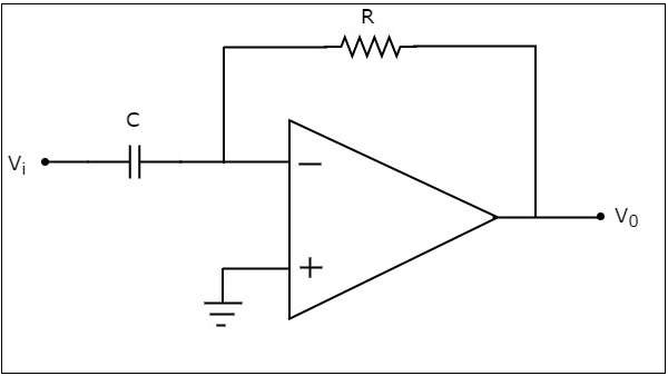
In the above circuit, the non-inverting input terminal of the op-amp is connected to ground. That means zero volts is applied to its non-inverting input terminal.
According to the virtual short concept, the voltage at the inverting input terminal of opamp will be equal to the voltage present at its non-inverting input terminal. So, the voltage at the inverting input terminal of op-amp will be zero volts.
The nodal equation at the inverting input terminal's node is −
$$C\frac{\text{d}(0-V_{i})}{\text{d}t}+\frac{0-V_0}{R}=0$$
$$=>-C\frac{\text{d}V_{i}}{\text{d}t}=\frac{V_0}{R}$$
$$=>V_{0}=-RC\frac{\text{d}V_{i}}{\text{d}t}$$
If $RC=1\sec$, then the output voltage $V_{0}$ will be −
$$V_{0}=-\frac{\text{d}V_{i}}{\text{d}t}$$
Thus, the op-amp based differentiator circuit shown above will produce an output, which is the differential of input voltage $V_{i}$, when the magnitudes of impedances of resistor and capacitor are reciprocal to each other.
Note that the output voltage $V_{0}$ is having a negative sign, which indicates that there exists a 1800 phase difference between the input and the output.
Integrator
An integrator is an electronic circuit that produces an output that is the integration of the applied input. This section discusses about the op-amp based integrator.
An op-amp based integrator produces an output, which is an integral of the input voltage applied to its inverting terminal. The circuit diagram of an op-amp based integrator is shown in the following figure −
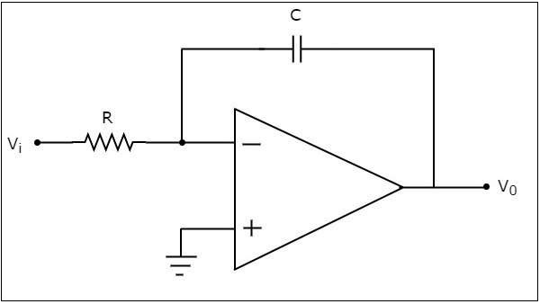
In the circuit shown above, the non-inverting input terminal of the op-amp is connected to ground. That means zero volts is applied to its non-inverting input terminal.
According to virtual short concept, the voltage at the inverting input terminal of op-amp will be equal to the voltage present at its non-inverting input terminal. So, the voltage at the inverting input terminal of op-amp will be zero volts.
The nodal equation at the inverting input terminal is −
$$\frac{0-V_i}{R}+C\frac{\text{d}(0-V_{0})}{\text{d}t}=0$$
$$=>\frac{-V_i}{R}=C\frac{\text{d}V_{0}}{\text{d}t}$$
$$=>\frac{\text{d}V_{0}}{\text{d}t}=-\frac{V_i}{RC}$$
$$=>{d}V_{0}=\left(-\frac{V_i}{RC}\right){\text{d}t}$$
Integrating both sides of the equation shown above, we get −
$$\int{d}V_{0}=\int\left(-\frac{V_i}{RC}\right){\text{d}t}$$
$$=>V_{0}=-\frac{1}{RC}\int V_{t}{\text{d}t}$$
If $RC=1\sec$, then the output voltage, $V_{0}$ will be −
$$V_{0}=-\int V_{i}{\text{d}t}$$
So, the op-amp based integrator circuit discussed above will produce an output, which is the integral of input voltage $V_{i}$, when the magnitude of impedances of resistor and capacitor are reciprocal to each other.
Note − The output voltage, $V_{0}$ is having a negative sign, which indicates that there exists 1800 phase difference between the input and the output.
