- Home
- Basics of Integrated Circuits Applications
- Basics Operational Amplifier
- Op-Amp applications
- Arithmetic Circuits
- Differentiator & Integrator
- Converters Of Electrical Quantities
- Comparators
- Log & Anti-Log Amplifiers
- Rectifiers
- Clippers
- Clampers
- Active Filters
- Sinusoidal Oscillators
- Waveform Generators
- 555 Timer
- Phase Locked Loop Ic
- Voltage Regulators
- Data Converters
- Digital to Analog Converters
- DAC Example Problem
- Direct Type ADCs
- Indirect Type ADC
Arithmetic Circuits
In the previous chapter, we discussed about the basic applications of op-amp. Note that they come under the linear operations of an op-amp. In this chapter, let us discuss about arithmetic circuits, which are also linear applications of op-amp.
The electronic circuits, which perform arithmetic operations are called as arithmetic circuits. Using op-amps, you can build basic arithmetic circuits such as an adder and a subtractor. In this chapter, you will learn about each of them in detail.
Adder
An adder is an electronic circuit that produces an output, which is equal to the sum of the applied inputs. This section discusses about the op-amp based adder circuit.
An op-amp based adder produces an output equal to the sum of the input voltages applied at its inverting terminal. It is also called as a summing amplifier, since the output is an amplified one.
The circuit diagram of an op-amp based adder is shown in the following figure −
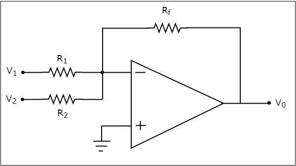
In the above circuit, the non-inverting input terminal of the op-amp is connected to ground. That means zero volts is applied at its non-inverting input terminal.
According to the virtual short concept, the voltage at the inverting input terminal of an op-amp is same as that of the voltage at its non-inverting input terminal. So, the voltage at the inverting input terminal of the op-amp will be zero volts.
The nodal equation at the inverting input terminal's node is
$$\frac{0-V_1}{R_1}+\frac{0-V_2}{R_2}+\frac{0-V_0}{R_f}=0$$
$$=>\frac{V_1}{R_1}-\frac{V_2}{R_2}=\frac{V_0}{R_f}$$
$$=>V_{0}=R_{f}\left(\frac{V_1}{R_1}+\frac{V_2}{R_2}\right)$$
If $R_{f}=R_{1}=R_{2}=R$, then the output voltage $V_{0}$ will be −
$$V_{0}=-R{}\left(\frac{V_1}{R}+\frac{V_2}{R}\right)$$
$$=>V_{0}=-(V_{1}+V_{2})$$
Therefore, the op-amp based adder circuit discussed above will produce the sum of the two input voltages $v_{1}$ and $v_{1}$, as the output, when all the resistors present in the circuit are of same value. Note that the output voltage $V_{0}$ of an adder circuit is having a negative sign, which indicates that there exists a 1800 phase difference between the input and the output.
Subtractor
A subtractor is an electronic circuit that produces an output, which is equal to the difference of the applied inputs. This section discusses about the op-amp based subtractor circuit.
An op-amp based subtractor produces an output equal to the difference of the input voltages applied at its inverting and non-inverting terminals. It is also called as a difference amplifier, since the output is an amplified one.
The circuit diagram of an op-amp based subtractor is shown in the following figure −
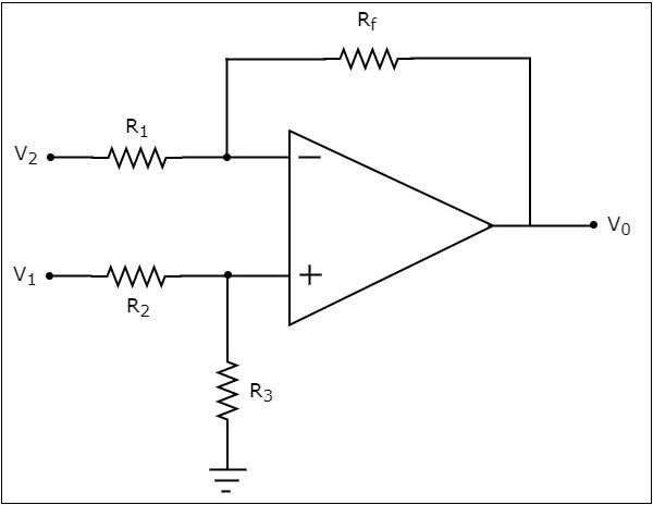
Now, let us find the expression for output voltage $V_{0}$ of the above circuit using superposition theorem using the following steps −
Step 1
Firstly, let us calculate the output voltage $V_{01}$ by considering only $V_{1}$.
For this, eliminate $V_{2}$ by making it short circuit. Then we obtain the modified circuit diagram as shown in the following figure −
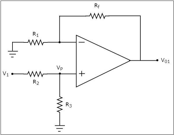
Now, using the voltage division principle, calculate the voltage at the non-inverting input terminal of the op-amp.
$$=>V_{p}=V_{1}\left(\frac{R_3}{R_2+R_3}\right)$$
Now, the above circuit looks like a non-inverting amplifier having input voltage $V_{p}$. Therefore, the output voltage $V_{01}$ of above circuit will be
$$V_{01}=V_{p}\left(1+\frac{R_f}{R_1}\right)$$
Substitute, the value of $V_{p}$ in above equation, we obtain the output voltage $V_{01}$ by considering only $V_{1}$, as −
$$V_{01}=V_{1}\left(\frac{R_3}{R_2+R_3}\right)\left(1+\frac{R_f}{R_1}\right)$$
Step 2
In this step, let us find the output voltage, $V_{02}$ by considering only $V_{2}$. Similar to that in the above step, eliminate $V_{1}$ by making it short circuit. The modified circuit diagram is shown in the following figure.
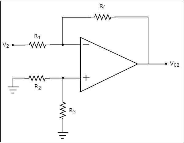
You can observe that the voltage at the non-inverting input terminal of the op-amp will be zero volts. It means, the above circuit is simply an inverting op-amp. Therefore, the output voltage $V_{02}$ of above circuit will be −
$$V_{02}=\left(-\frac{R_f}{R_1}\right)V_{2}$$
Step 3
In this step, we will obtain the output voltage $V_{0}$ of the subtractor circuit by adding the output voltages obtained in Step1 and Step2. Mathematically, it can be written as
$$V_{0}=V_{01}+V_{02}$$
Substituting the values of $V_{01}$ and $V_{02}$ in the above equation, we get −
$$V_{0}=V_{1}\left(\frac{R_3}{R_2+R_3}\right)\left(1+\frac{R_f}{R_1}\right)+\left(-\frac{R_f}{R_1}\right)V_{2}$$
$$=>V_{0}=V_{1}\left(\frac{R_3}{R_2+R_3}\right)\left(1+\frac{R_f}{R_1}\right)-\left(\frac{R_f}{R_1}\right)V_{2}$$
If $R_{f}=R_{1}=R_{2}=R_{3}=R$, then the output voltage $V_{0}$ will be
$$V_{0}=V_{1}\left(\frac{R}{R+R}\right)\left(1+\frac{R}{R}\right)-\left(\frac{R}{R}\right)V_{2}$$
$$=>V_{0}=V_{1}\left(\frac{R}{2R}\right)(2)-(1)V_{2}$$
$$V_{0}=V_{1}-V_{2}$$
Thus, the op-amp based subtractor circuit discussed above will produce an output, which is the difference of two input voltages $V_{1}$ and $V_{2}$, when all the resistors present in the circuit are of same value.
