
Article Categories
- All Categories
-
 Data Structure
-
 Networking
-
 RDBMS
RDBMS
-
 Operating System
-
 Java
Java
-
 MS Excel
-
 iOS
iOS
-
 HTML
HTML
-
 CSS
CSS
-
 Android
-
 Python
-
 C Programming
-
 C++
C++
-
 C#
C#
-
 MongoDB
-
 MySQL
MySQL
-
 Javascript
-
 PHP
PHP
Interfacing 8279 Display with 8085 Microprocessor
The Intel 8279 is used for keyboard interfacing but it can also be used for multiplexed 7-segment LED display interfacing. To display a character into 7-segment display we have to store 7-segment code in a display RAM location. The display RAM of this chip can store 16 bytes of data.
Write to Display RAM
To write to the display RAM one special command is needed to be applied on the 8279 control port. The following pattern is showing the RAM command that is written to the control port of 8279.
| 1 |
0 |
0 |
Ai |
A |
A |
A |
A |
The first three bits are 100. It indicates ‘ Write to Display RAM’command. The last 4-bits are AAAA. These are used to select the RAM location. The Ai bit is the auto-increment bit.
As an example says we want to write at RAM location 4 in auto-increment mode, then the RAM pointer is loaded with the address 4. When the processor writes to the display RAM for the first time, it will beRAM location 4. Then the address is incremented to 5 and so on.
This following code achieves the objective of displaying ABCD in the address field.
MVI A, 10010100
OUT D1H //Write display location 4 in auto increment mode.
MVI A, A1H
OUT D0H //send A1H at RAM location 4
MVI A, C6H
OUT D0H //send C6H at RAM location 5
MVI A, 83H
OUT D0H //send 83H at RAM location 6
MVI A, 88H
OUT D0H //send 88H at RAM location 7
Read from Display RAM
To read from any RAM location of 8279, one special command is needed to be applied on the8279 control port. The following pattern is showing the RAM command that is read from the control port of 8279.
| 0 |
1 |
1 |
Ai |
A |
A |
A |
A |
The first three bits are 011. It indicates ‘Read from Display RAM’command. The last 4-bits are AAAA. These are used to select the RAM location. The Ai bit is the auto-increment bit. The display RAM is the same for reading and writes operation.
As an example say we want to read from RAM location 4 in auto-increment mode, then the RAM pointer is loaded with the address 4.
If there are A1 and C6 are stored at RAM location 4 and 5, then the following code achieves the objective of reading AB from the RAM.
MVI A, 01110100
OUT D1H //Read from display location 4 in auto increment mode.
IN D0H //Load A with A1, the address value is now pointing to
5
IN D0H //Load A with C6
There are two modes of 7-segment display operations. These modes are:
Decoded Mode of operation
Encoded Mode of operation
Decoded Mode of Operation
In this mode no external decoders are needed, one scan line is made logic 0 at a time and this selects a particular LED position for the display purpose. In this mode, four displays can be attached. The following table is showing the pattern shown by the SL3-0 by 8279 for displays.
| SL3-0 |
Selected LED |
|---|---|
| 1110 |
LED 0 |
| 1101 |
LED 1 |
| 1011 |
LED 2 |
| 0111 |
LED 3 |
The following figure illustrates how to interface common anode 7-segment LED displays in decoded mode. First of all, the 8279 chip outputs1110 on SL3-0.This results in display 0 receiving the 5V power supply to its anode and all other LEDs are receiving 0V for their anodes.
The contents of display RAM location 0 are output on A3-0 and B3-0 by the 8279. All of the displays are getting this information, but the character is displayed only on the display-0 which receives the 5V power supply.
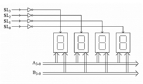
Next, the select lines SL3-0 is loaded with 1101, so the second display will be selected and the content of the display RAM has reflected the display. Thus the displays are showing different characters by refreshing the contents.
Encoded Mode of Operation
This mode is widely used because in this mode we can connect at most 16 displays. Here external decoders are needed. This mode can be used for 8-character or 16-character display. For 8-character display, only SL2-0 pins are used. The SL3 is unused. For 16-character display, all of the select lines are used.
The following figure illustrates how to interface common anode 7-segment LED displays in encoded mode. In this diagram, we are assuming that16-displays are connected. In this case, the SL3-0 values are changing from 0000 to 1111, so only the selected display is getting the 5v power supply in its anode, and others are getting 0V.
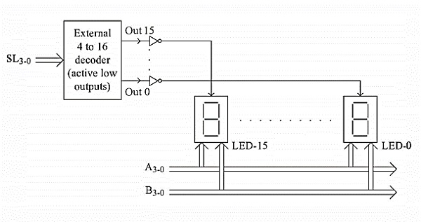
Next, the select lines SL3-0 is loaded with 1101, so the second display will be selected and the content of the display RAM has reflected the display. Thus the displays are showing different characters by refreshing the contents.

4K+ Views
