 Data Structure
 Networking
 RDBMS
RDBMS Operating System
 Java
Java MS Excel
 iOS
iOS HTML
HTML CSS
CSS Android
 Python
 C Programming
 C++
C++ C#
C# MongoDB
 MySQL
MySQL Javascript
 PHP
PHP
- Selected Reading
- UPSC IAS Exams Notes
- Developer's Best Practices
- Questions and Answers
- Effective Resume Writing
- HR Interview Questions
- Computer Glossary
- Who is Who
Interfacing 8253 (Timer IC) with 8085 Microprocessor
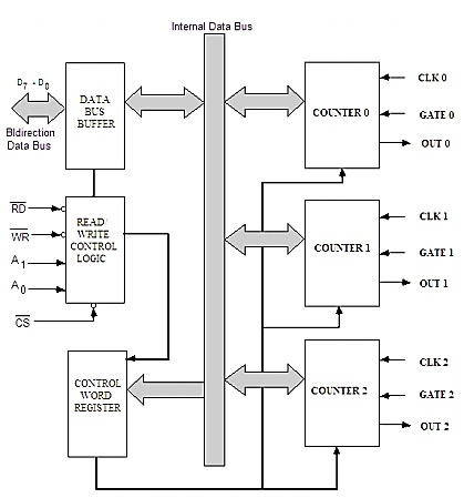
The Intel 8253 is programmable Interval Timers (PTIs) designed for microprocessors toper form timing and counting functions using three 16-bit registers. Each counter has 2 input pins, i.e. Clock & Gate, and 1 pin for“OUT” output. To operate a counter, a 16-bit count is loaded in its register. On command, it begins to decrement the count until it reaches 0, then it generates a pulse that can be used to interrupt the CPU.
Features of 8253
It has three independent 16-bit down counters.
It can handle inputs from DC to 10MHz.
These three counters can be programmed for either binary or BCD count.
It is compatible with almost all microprocessors.
8254has a powerful command called READ BACK command, which allows the user to check the count value, the programmed mode, the current mode, and the current status of the counter.
The block diagram of 8253

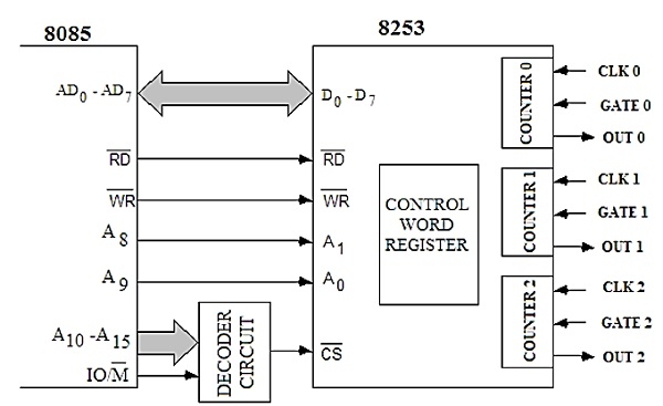
Interfacing 8253 with 8085
Now let us see how to interface this 8253 timer chip with the Intel 8085 microprocessor. From the following picture, we can see that the data bus D7-0 of 8085 is connected to the data pins D7 to D0 of 8253. So the higher order address bus is used as decoder input to select the chip and the A8 and A9 of 8085 are connected to the pin A1 and A0 respectively to select the counter.

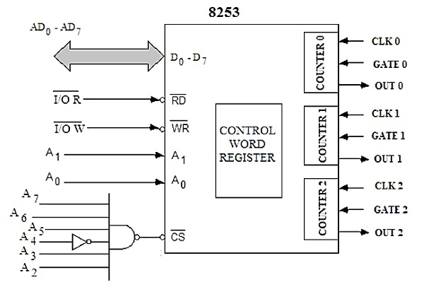
In the next diagram, we can get the chip select logic of 8253. In that diagram, we can easily find that when A3-2 and A7-5 are at logic 0 and A4 at logic 1, then only the chip select CS pin of 8253 will be enabled.

This table is showing how the counter is being selected by using A1 and A0 pins of 8253.
|
CS |
HEX Address |
Counter Selection |
|||||||
|---|---|---|---|---|---|---|---|---|---|
| A7 |
A6 |
A5 |
A4 |
A3 |
A2 |
A1 |
A0 |
||
| 0 |
0 |
0 |
1 |
0 |
0 |
0 |
0 |
10H |
Counter 0 |
| 0 |
0 |
0 |
1 |
0 |
0 |
0 |
1 |
11H |
Counter 1 |
| 0 |
0 |
0 |
1 |
0 |
0 |
1 |
0 |
12H |
Counter 2 |
| 0 |
0 |
0 |
1 |
0 |
0 |
1 |
1 |
13H |
Control Word Register |
By using the IN and OUT instruction the counter selection and Control Word Register (CWR) setup can be done. If the Accumulator is holding content to load CWR, then by using OUT 13H the CWR will be set. Similarly, by using IN instruction we can get the value of counter value, like IN 11H will get the value from counter 1 and so on.
So the following four steps are needed for counter operations:
Initialize 8253 chip
Load Control word register with Control Word value
Load Lower Order count value
Load Higher Order count value
Let us see a program to load counter 2 in mode 1 with a count value 500010 in mode 0. Also, read the count value on a fly.
At first, to initialize the8253, the Control word will be B2H
| Counter 2 |
Load LS and then MS |
Mode 1 selection |
0 for Binary |
||||
|---|---|---|---|---|---|---|---|
| 1 |
0 |
1 |
1 |
0 |
0 |
1 |
0 |
Now the control word for latching operation for counter 2 is 80H.
| Counter 2 |
Latching Option |
Don’t Care |
|||||
|---|---|---|---|---|---|---|---|
| 1 |
0 |
0 |
0 |
0 |
0 |
0 |
0 |
We will load 500010 into the counter. The hexadecimal equivalent of 500010 is 1388H.
MVI A, B2H ;Load B2H as initialization byte for counter
OUT 13H ;Write Acc content CWR
MVI A, 88H ;Load LS byte of count value
OUT 12H ;Send to Counter 2
MVI A, 13H ;Load MS byte of count value
OUT 12H ;Send to Counter 2
MVI D, 00H ;clear the register D
L1: MVI A, 80H ;Set a with control word 80H of counter 2
OUT 13H ;Write Acc content CWR
IN 12H ;Read LS value of counter value
MOV B, A ;store LS value to B
IN 12H ;Read MS value of counter value
ORA B ;OR LS and MS to set Z flag
JNZ L1 ;If Z flag is not set, jump to Loop
HLT ;Halt the program

