
Article Categories
- All Categories
-
 Data Structure
-
 Networking
-
 RDBMS
RDBMS
-
 Operating System
-
 Java
Java
-
 MS Excel
-
 iOS
iOS
-
 HTML
HTML
-
 CSS
CSS
-
 Android
-
 Python
-
 C Programming
-
 C++
C++
-
 C#
C#
-
 MongoDB
-
 MySQL
MySQL
-
 Javascript
-
 PHP
PHP
-
 Economics & Finance
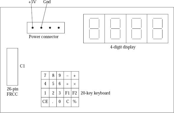
Display interface using serial transfer in 8085 Microprocessor
In this module we have explained the complete interface of four numbers segmented into seven parts having the Light Emitting Diode which uses a serial data transfer scheme. The portion which is displayed of the interface has 4 LEDS comprises of 7-segments LEDs as we can see from the physical layout of the interface. The connection to the interface is done by the ALS-8085 kit which uses a flat table of 26 crores. We connect the connector C1 to the interface to the Input Output connector P3 on the ALS kit. There is a power supply of of +5 V and Gnd that gets connected to the interface.
Keyboard/display mode set command: It configures the 8279 keyboard and display mode. The keyboard/display mode format is set command that is written to the control port of 8279 as follows.
![]()
When the Most Significant bits of the control port are 000 it signifies the keyboard/display mode commands are
|
P |
Q |
R |
S |
X |
Y |
|---|---|---|---|---|---|
| 0 |
0 |
0 |
0 |
1 |
0 |
| 0 |
0 |
0 |
1 |
0 |
0 |
| 0 |
0 |
1 |
0 |
1 |
0 |
| 0 |
0 |
1 |
1 |
0 |
0 |
| 0 |
1 |
0 |
0 |
1 |
0 |
| 0 |
1 |
0 |
1 |
0 |
0 |
| 0 |
1 |
1 |
0 |
1 |
0 |
| 0 |
1 |
1 |
1 |
0 |
0 |
| 1 |
0 |
0 |
0 |
0 |
1 |
| 1 |
0 |
0 |
1 |
0 |
1 |
| 1 |
0 |
1 |
0 |
1 |
0 |
| 1 |
0 |
1 |
1 |
0 |
0 |
| 1 |
1 |
0 |
0 |
0 |
0 |
| 1 |
1 |
0 |
1 |
1 |
1 |
| 1 |
1 |
1 |
0 |
0 |
0 |
| 1 |
1 |
1 |
1 |
0 |
0 |
This is the truth table
Four 8-bit serial shift registers are used by the interface. The outputs get connected to the shift registers of four bits. When we use this interface it is necessary for the configuration of the ports of 8255.
Output port B;
Output as the upper portion of port C;
Configuring ports is of less importance.

472 Views
