
Article Categories
- All Categories
-
 Data Structure
-
 Networking
-
 RDBMS
RDBMS
-
 Operating System
-
 Java
Java
-
 MS Excel
-
 iOS
iOS
-
 HTML
HTML
-
 CSS
CSS
-
 Android
-
 Python
-
 C Programming
-
 C++
C++
-
 C#
C#
-
 MongoDB
-
 MySQL
MySQL
-
 Javascript
-
 PHP
PHP
Interfacing 7(Seven) Segment Display to 8085 Microprocessor
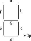
An output device which is very common is, especially in the kit of 8085 microprocessor and it is the Light Emitting Diode consisting of seven segments. Moreover, we have eight segments in a LED display consisting of 7 segments which includes ‘.’, consisting of character 8 and having a decimal point just next to it. We denote the segments as ‘a, b, c, d, e, f, g, and dp’ where dp signifies ‘.’ which is the decimal point. Moreover, these are LEDs or together a series of Light Emitting Diodes. We have shown the internal circuit comprising of a display of seven segment is as shown in Fig 2
a 7-segment display is as shown in the following Fig.
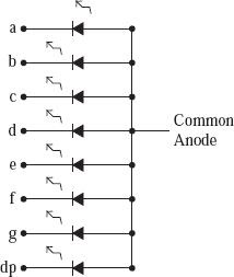
There are two types of 7-segment LED: They are the common anode type and the common cathode type. We have discussed the common anode-type which is 7 segmented Light Emitting Diode. In the LED which is common anode and is 7-segmented, here we connect all the eight LED anodes together and the eight external pin is brought to display. And this pin gets connected to a DC supply of +5 Volt. The cathode ends of the eight segments are brought out on the pins of the display.
The use of 74373 latch for interfacing a 7-segment display is shown in the following Fig.
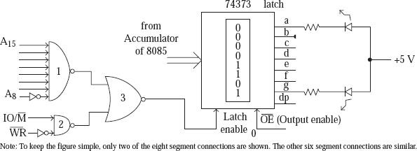
In thethe 74373 latch is used as an I/O mapped I/O port with the port address as FEH. This could be easily verified from the chip select circuit used in the figure. The following instructions are to be executed to display character ‘3’ on the 7-segment display. The corresponding program to send 0DH to the port FEH will be -
MVI A, 0DH
OUT FEH
Using MVI instruction we are initializing Accumulator (A) with Byte 0DH i.e. 0000 1101. Then it will be sent to the port FEH by the instruction OUT.

15K+ Views
