
Article Categories
- All Categories
-
 Data Structure
-
 Networking
-
 RDBMS
RDBMS
-
 Operating System
-
 Java
Java
-
 MS Excel
-
 iOS
iOS
-
 HTML
HTML
-
 CSS
CSS
-
 Android
-
 Python
-
 C Programming
-
 C++
C++
-
 C#
C#
-
 MongoDB
-
 MySQL
MySQL
-
 Javascript
-
 PHP
PHP
-
 Economics & Finance
Interfacing 8279 Keyboard with 8085 Microprocessor
Here we will see how 8279 Chip can be used to interface a matrix keyboard with 8085 microprocessors. This chip can be used either keyboard/display interfacing mode or as a strobed input port. But generally, it is used as keyboard interfacing.
The keyboard interfacing schemes can also be divided into two modes. These modes are
Decoded mode of operation
Encoded mode of operation
Decoded Mode of Operation
In this mode, the matrix keyboard can have only four rows. These four rows can be selected by using SL3-0 select lines. There are eight columns. These can be selected using RL7-0 these eight column lines. So there are 4 * 8 = 32 keys. At the intersection of each row and column, there is a key. There are another two keys. These keys are Shift key and the Ctrl key, these two keys are not the part of the matrix. The key structure looks like this -
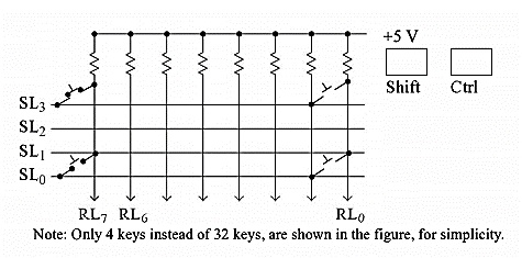
In the decoded mode the 8279 scans the keys by making logic 0 for each row at a time, and then each of the eight columns is read. The following table is showing the pattern shown by the SL3-0 by 8279 for scanning keyboard.
| SL3-0 |
Row Being Scanned |
|---|---|
| 1110 |
Row 0 |
| 1101 |
Row 1 |
| 1011 |
Row 2 |
| 0111 |
Row 3 |
Let us see an example of this keyboard scanning mechanism. Let us consider that currently, it is scanning row 3 by sending the select line values 0111, and the received information is 10111111 from RL7-0. It is indicating that the RL6 is at logic 0. So for this data, the FIFO RAM will be loaded like below.
|
|
Indicates Row 3 |
Indicates Column 6 |
|||||
|---|---|---|---|---|---|---|---|
| Ctrl |
Shift |
0 |
1 |
1 |
1 |
1 |
0 |
The LS 3 bits indicating the column numbers (Here 110 means the column 6) and next 3 bits are indicating the row number (Here 011 for row 3). As there are four rows in the keyboard so 2-bits are sufficient, but there are three bits (One additional bit) for row selection.
When the ctrl and shift buttons are not pressed, then these two fields will hold 1. After scanning the keyboard key, the IRQ is activated by 8279. This IRQ is connected with the Interrupt Request pin of the 8085. When the processor reads FIFO RAM, the IRQ pin becomes 0. When the processor is in disabled interrupt state, then the key content is stored into the FIFO RAM. If another key is pressed in that time, that information is added after the previous key information in FIFO RAM like a queue structure.
Status Register
The status register is holding important information about the FIFO RAM. The structure of this register is like below.
| Du |
S/E |
O |
U |
F |
N |
N |
N |
The last three bits are used to represent the number of characters present in FIFO RAM. It starts from 000 and incremented by 1. When one key data is sent by enabling the IRQ pin and the processor is reading the content of FIFO RAM, then these values are decremented by 1.
When the interrupts of the processor are disabled, and the user is pressing seven keys, then the value of the last three bits will be 111. So if another key is pressed, the F flag will be set to 1, and three bits will become 000. This flag will indicate the FIFO RAM is full. Now if another key is pressed when the FIFO RAM is full, it will overwrite the last character of the FIFO RAM. It will generate an Over-run error. It will set the O flag. This O flag indicates the Over-run error. Similarly, when the F flag is 0, and the last three bits are also 000, then it indicates that the FIFO RAM is not full and also it has no character to read. In this situation, if the processor is trying to read the FIFO RAM, it will generate Underflow error by enabling the U flag.
Encoded Mode of Operation
In the decoded mode there are only four rows. In most of the cases, the 8279 is used in Encoded mode of operation. In this mode, we can set eight rows and eight columns to connect 64 keys. Like the decoded mode, it also has shift and control key. So by adding these two with 64, there are 66 keys.
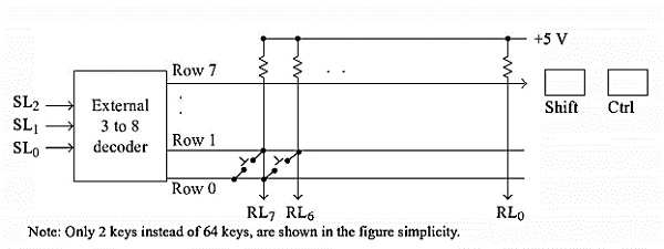
From this diagram, we can see that one external 3:8 decoder is used. To the decoder, the SL2-0 is connected. The SL3 is not used. The decoder output is connected with the eight rows of the matrix. The following table is showing the pattern shown by theSL2-0 by 8279 for scanning keyboard.
| SL2-0 |
Row Being Scanned |
|---|---|
| 000 |
Row 0 |
| 001 |
Row 1 |
| 010 |
Row 2 |
| 011 |
Row 3 |
| 100 |
Row 4 |
| 101 |
Row 5 |
| 110 |
Row 6 |
| 111 |
Row 7 |
Let us see an example of this keyboard scanning mechanism. Let us consider that currently, it is scanning row 5 by sending the select line values 101, and the received information is 10111111 from RL7-0. It is indicating that the RL6 is at logic 0. So for this data, the FIFO RAM will be loaded like below.
|
|
Indicates Row 5 |
Indicates Column 6 |
|||||
|---|---|---|---|---|---|---|---|
| Ctrl |
Shift |
1 |
0 |
1 |
1 |
1 |
0 |
The LS 3 bits are indicating the column numbers (Here 110 means the column 6) and next3 bits are indicating the row number (Here 101 for row 5). Additional two keys area are also present in the FIFO RAM.

3K+ Views
