- Digital Communication - Home
- Analog to Digital
- Pulse Code Modulation
- Sampling
- Quantization
- Differential PCM
- Delta Modulation
- Techniques
- Line Codes
- Data Encoding Techniques
- Pulse Shaping
- Digital Modulation Techniques
- Amplitude Shift Keying
- Frequency Shift Keying
- Phase Shift Keying
- Quadrature Phase Shift Keying
- Differential Phase Shift Keying
- M-ary Encoding
- Information Theory
- Source Coding Theorem
- Channel Coding Theorem
- Error Control Coding
- Spread Spectrum Modulation
Digital Communication - Techniques
There are a few techniques which have paved the basic path to digital communication processes. For the signals to get digitized, we have the sampling and quantizing techniques.
For them to be represented mathematically, we have LPC and digital multiplexing techniques. These digital modulation techniques are further discussed.
Linear Predictive Coding
Linear Predictive Coding (LPC) is a tool which represents digital speech signals in linear predictive model. This is mostly used in audio signal processing, speech synthesis, speech recognition, etc.
Linear prediction is based on the idea that the current sample is based on the linear combination of past samples. The analysis estimates the values of a discrete-time signal as a linear function of the previous samples.
The spectral envelope is represented in a compressed form, using the information of the linear predictive model. This can be mathematically represented as −
$s(n) = \displaystyle\sum\limits_{k = 1}^p \alpha_k s(n - k)$ for some value of p and αk
Where
s(n) is the current speech sample
k is a particular sample
p is the most recent value
αk is the predictor co-efficient
s(n - k) is the previous speech sample
For LPC, the predictor co-efficient values are determined by minimizing the sum of squared differences (over a finite interval) between the actual speech samples and the linearly predicted ones.
This is a very useful method for encoding speech at a low bit rate. The LPC method is very close to the Fast Fourier Transform (FFT) method.
Multiplexing
Multiplexing is the process of combining multiple signals into one signal, over a shared medium. These signals, if analog in nature, the process is called as analog multiplexing. If digital signals are multiplexed, it is called as digital multiplexing.
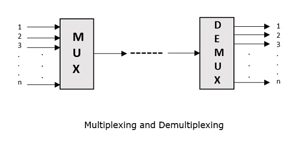
Multiplexing was first developed in telephony. A number of signals were combined to send through a single cable. The process of multiplexing divides a communication channel into several number of logical channels, allotting each one for a different message signal or a data stream to be transferred. The device that does multiplexing, can be called as a MUX. The reverse process, i.e., extracting the number of channels from one, which is done at the receiver is called as de-multiplexing. The device which does de-multiplexing is called as DEMUX.
The following figures represent MUX and DEMUX. Their primary use is in the field of communications.
Types of Multiplexers
There are mainly two types of multiplexers, namely analog and digital. They are further divided into FDM, WDM, and TDM. The following figure gives a detailed idea on this classification.
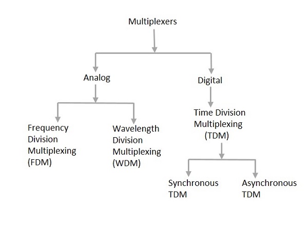
Actually, there are many types of multiplexing techniques. Of them all, we have the main types with general classification, mentioned in the above figure.
Analog Multiplexing
The analog multiplexing techniques involve signals which are analog in nature. The analog signals are multiplexed according to their frequency (FDM) or wavelength (WDM).
Frequency Division Multiplexing (FDM)
In analog multiplexing, the most used technique is Frequency Division Multiplexing (FDM). This technique uses various frequencies to combine streams of data, for sending them on a communication medium, as a single signal.
Example − A traditional television transmitter, which sends a number of channels through a single cable, uses FDM.
Wavelength Division Multiplexing (WDM)
Wavelength Division multiplexing is an analog technique, in which many data streams of different wavelengths are transmitted in the light spectrum. If the wavelength increases, the frequency of the signal decreases. A prism which can turn different wavelengths into a single line, can be used at the output of MUX and input of DEMUX.
Example − Optical fiber communications use WDM technique to merge different wavelengths into a single light for communication.
Digital Multiplexing
The term digital represents the discrete bits of information. Hence, the available data is in the form of frames or packets, which are discrete.
Time Division Multiplexing (TDM)
In TDM, the time frame is divided into slots. This technique is used to transmit a signal over a single communication channel, by allotting one slot for each message.
Of all the types of TDM, the main ones are Synchronous and Asynchronous TDM.
Synchronous TDM
In Synchronous TDM, the input is connected to a frame. If there are n number of connections, then the frame is divided into n time slots. One slot is allocated for each input line.
In this technique, the sampling rate is common to all signals and hence the same clock input is given. The MUX allocates the same slot to each device at all times.
Asynchronous TDM
In Asynchronous TDM, the sampling rate is different for each of the signals and a common clock is not required. If the allotted device, for a time-slot, transmits nothing and sits idle, then that slot is allotted to another device, unlike synchronous. This type of TDM is used in Asynchronous transfer mode networks.
Regenerative Repeater
For any communication system to be reliable, it should transmit and receive the signals effectively, without any loss. A PCM wave, after transmitting through a channel, gets distorted due to the noise introduced by the channel.
The regenerative pulse compared with the original and received pulse, will be as shown in the following figure.
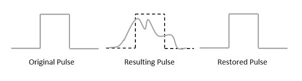
For a better reproduction of the signal, a circuit called as regenerative repeater is employed in the path before the receiver. This helps in restoring the signals from the losses occurred. Following is the diagrammatical representation.
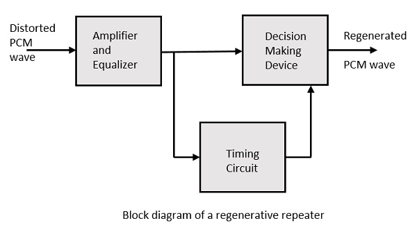
This consists of an equalizer along with an amplifier, a timing circuit, and a decision making device. Their working of each of the components is detailed as follows.
Equalizer
The channel produces amplitude and phase distortions to the signals. This is due to the transmission characteristics of the channel. The Equalizer circuit compensates these losses by shaping the received pulses.
Timing Circuit
To obtain a quality output, the sampling of the pulses should be done where the signal to noise ratio (SNR) is maximum. To achieve this perfect sampling, a periodic pulse train has to be derived from the received pulses, which is done by the timing circuit.
Hence, the timing circuit, allots the timing interval for sampling at high SNR, through the received pulses.
Decision Device
The timing circuit determines the sampling times. The decision device is enabled at these sampling times. The decision device decides its output based on whether the amplitude of the quantized pulse and the noise, exceeds a pre-determined value or not.
These are few of the techniques used in digital communications. There are other important techniques to be learned, called as data encoding techniques. Let us learn about them in the subsequent chapters, after taking a look at the line codes.
