- Digital Communication - Home
- Analog to Digital
- Pulse Code Modulation
- Sampling
- Quantization
- Differential PCM
- Delta Modulation
- Techniques
- Line Codes
- Data Encoding Techniques
- Pulse Shaping
- Digital Modulation Techniques
- Amplitude Shift Keying
- Frequency Shift Keying
- Phase Shift Keying
- Quadrature Phase Shift Keying
- Differential Phase Shift Keying
- M-ary Encoding
- Information Theory
- Source Coding Theorem
- Channel Coding Theorem
- Error Control Coding
- Spread Spectrum Modulation
Digital Communication - Pulse Shaping
After going through different types of coding techniques, we have an idea on how the data is prone to distortion and how the measures are taken to prevent it from getting affected so as to establish a reliable communication.
There is another important distortion which is most likely to occur, called as Inter-Symbol Interference (ISI).
Inter Symbol Interference
This is a form of distortion of a signal, in which one or more symbols interfere with subsequent signals, causing noise or delivering a poor output.
Causes of ISI
The main causes of ISI are −
- Multi-path Propagation
- Non-linear frequency in channels
The ISI is unwanted and should be completely eliminated to get a clean output. The causes of ISI should also be resolved in order to lessen its effect.
To view ISI in a mathematical form present in the receiver output, we can consider the receiver output.
The receiving filter output $y(t)$ is sampled at time $t_i = iT_b$ (with i taking on integer values), yielding −
$y(t_i) = \mu \displaystyle\sum\limits_{k = -\infty}^{\infty}a_kp(iT_b - kT_b)$
$= \mu a_i + \mu \displaystyle\sum\limits_{k = -\infty \\ k \neq i}^{\infty}a_kp(iT_b - kT_b)$
In the above equation, the first term $\mu a_i$ is produced by the ith transmitted bit.
The second term represents the residual effect of all other transmitted bits on the decoding of the ith bit. This residual effect is called as Inter Symbol Interference.
In the absence of ISI, the output will be −
$$y(t_i) = \mu a_i$$
This equation shows that the ith bit transmitted is correctly reproduced. However, the presence of ISI introduces bit errors and distortions in the output.
While designing the transmitter or a receiver, it is important that you minimize the effects of ISI, so as to receive the output with the least possible error rate.
Correlative Coding
So far, weve discussed that ISI is an unwanted phenomenon and degrades the signal. But the same ISI if used in a controlled manner, is possible to achieve a bit rate of 2W bits per second in a channel of bandwidth W Hertz. Such a scheme is called as Correlative Coding or Partial response signaling schemes.
Since the amount of ISI is known, it is easy to design the receiver according to the requirement so as to avoid the effect of ISI on the signal. The basic idea of correlative coding is achieved by considering an example of Duo-binary Signaling.
Duo-binary Signaling
The name duo-binary means doubling the binary systems transmission capability. To understand this, let us consider a binary input sequence {ak} consisting of uncorrelated binary digits each having a duration Ta seconds. In this, the signal 1 is represented by a +1 volt and the symbol 0 by a -1 volt.
Therefore, the duo-binary coder output ck is given as the sum of present binary digit ak and the previous value ak-1 as shown in the following equation.
$$c_k = a_k + a_{k-1}$$
The above equation states that the input sequence of uncorrelated binary sequence {ak} is changed into a sequence of correlated three level pulses {ck}. This correlation between the pulses may be understood as introducing ISI in the transmitted signal in an artificial manner.
Eye Pattern
An effective way to study the effects of ISI is the Eye Pattern. The name Eye Pattern was given from its resemblance to the human eye for binary waves. The interior region of the eye pattern is called the eye opening. The following figure shows the image of an eye-pattern.
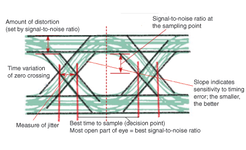
Jitter is the short-term variation of the instant of digital signal, from its ideal position, which may lead to data errors.
When the effect of ISI increases, traces from the upper portion to the lower portion of the eye opening increases and the eye gets completely closed, if ISI is very high.
An eye pattern provides the following information about a particular system.
Actual eye patterns are used to estimate the bit error rate and the signal-to-noise ratio.
The width of the eye opening defines the time interval over which the received wave can be sampled without error from ISI.
The instant of time when the eye opening is wide, will be the preferred time for sampling.
The rate of the closure of the eye, according to the sampling time, determines how sensitive the system is to the timing error.
The height of the eye opening, at a specified sampling time, defines the margin over noise.
Hence, the interpretation of eye pattern is an important consideration.
Equalization
For reliable communication to be established, we need to have a quality output. The transmission losses of the channel and other factors affecting the quality of the signal, have to be treated. The most occurring loss, as we have discussed, is the ISI.
To make the signal free from ISI, and to ensure a maximum signal to noise ratio, we need to implement a method called Equalization. The following figure shows an equalizer in the receiver portion of the communication system.
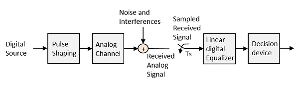
The noise and interferences which are denoted in the figure, are likely to occur, during transmission. The regenerative repeater has an equalizer circuit, which compensates the transmission losses by shaping the circuit. The Equalizer is feasible to get implemented.
Error Probability and Figure-of-merit
The rate at which data can be communicated is called the data rate. The rate at which error occurs in the bits, while transmitting data is called the Bit Error Rate (BER).
The probability of the occurrence of BER is the Error Probability. The increase in Signal to Noise Ratio (SNR) decreases the BER, hence the Error Probability also gets decreased.
In an Analog receiver, the figure of merit at the detection process can be termed as the ratio of output SNR to the input SNR. A greater value of figure-of-merit will be an advantage.
