- Digital Communication - Home
- Analog to Digital
- Pulse Code Modulation
- Sampling
- Quantization
- Differential PCM
- Delta Modulation
- Techniques
- Line Codes
- Data Encoding Techniques
- Pulse Shaping
- Digital Modulation Techniques
- Amplitude Shift Keying
- Frequency Shift Keying
- Phase Shift Keying
- Quadrature Phase Shift Keying
- Differential Phase Shift Keying
- M-ary Encoding
- Information Theory
- Source Coding Theorem
- Channel Coding Theorem
- Error Control Coding
- Spread Spectrum Modulation
Digital Communication - Differential PCM
For the samples that are highly correlated, when encoded by PCM technique, leave redundant information behind. To process this redundant information and to have a better output, it is a wise decision to take a predicted sampled value, assumed from its previous output and summarize them with the quantized values. Such a process is called as Differential PCM (DPCM) technique.
DPCM Transmitter
The DPCM Transmitter consists of Quantizer and Predictor with two summer circuits. Following is the block diagram of DPCM transmitter.
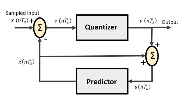
The signals at each point are named as −
$x(nT_{s})$ is the sampled input
$\widehat{x}(nT_{s})$ is the predicted sample
$e(nT_{s})$ is the difference of sampled input and predicted output, often called as prediction error
$v(nT_{s})$ is the quantized output
$u(nT_{s})$ is the predictor input which is actually the summer output of the predictor output and the quantizer output
The predictor produces the assumed samples from the previous outputs of the transmitter circuit. The input to this predictor is the quantized versions of the input signal $x(nT_{s})$.
Quantizer Output is represented as −
$$v(nT_{s}) = Q[e(nT_{s})]$$ $$= e(nT_{s}) + q(nT_{s})$$Where q (nTs) is the quantization error
Predictor input is the sum of quantizer output and predictor output,
$$u(nT_{s}) = \widehat{x}(nT_{s}) + v(nT_{s})$$ $$u(nT_{s}) = \widehat{x}(nT_{s}) + e(nT_{s}) + q(nT_{s})$$ $$u(nT_{s}) = x(nT_{s}) + q(nT_{s})$$The same predictor circuit is used in the decoder to reconstruct the original input.
DPCM Receiver
The block diagram of DPCM Receiver consists of a decoder, a predictor, and a summer circuit. Following is the diagram of DPCM Receiver.
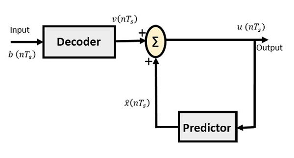
The notation of the signals is the same as the previous ones. In the absence of noise, the encoded receiver input will be the same as the encoded transmitter output.
As mentioned before, the predictor assumes a value, based on the previous outputs. The input given to the decoder is processed and that output is summed up with the output of the predictor, to obtain a better output.
