
Article Categories
- All Categories
-
 Data Structure
-
 Networking
-
 RDBMS
RDBMS
-
 Operating System
-
 Java
Java
-
 MS Excel
-
 iOS
iOS
-
 HTML
HTML
-
 CSS
CSS
-
 Android
-
 Python
-
 C Programming
-
 C++
C++
-
 C#
C#
-
 MongoDB
-
 MySQL
MySQL
-
 Javascript
-
 PHP
PHP
-
 Economics & Finance
Capacitors in AC Circuits
Consider the circuit consisting of a capacitor (C) only. When an alternating voltage is applied across the capacitor, the capacitor being charged in one direction and then in the other as the voltage reverses. Due to the application of alternating voltage across the capacitor the electrons move to and fro around the circuit, thus constituting alternating current.

Let the equation of the applied alternating voltage is
$$\mathrm{\nu= V_{m} sin(\omega t)}\:\:\:….. (1)$$
As a result of the alternating voltage (v), alternating current will flow through the circuit (i). Let at any instant q is the charge on plates of the capacitor. Thus,
$$\mathrm{q=C \nu = CV_{m}sin(\omega t)}$$
$$\mathrm{∴\:Circuit\:current\:i = \frac{dq}{dt}=\frac{d}{dt}(CV_{m}sin(\omega t)) = \omega CV_{m} cos(\omega t)}$$
$$\mathrm{\Rightarrow i = \omega CV_{m} sin(\omega t + 90^{\circ})}\:\:\: … (2)$$
When sin(ωt + 90°) = 1, then the value of i will be maximum, i.e.
$$\mathrm{I_{m}= \omega CV_{m}}$$
Substituting value of Im in equation (2), we obtain,
$$\mathrm{i=I_{m}sin(\omega t + 90^{\circ})}\:\:\ :… (3)$$
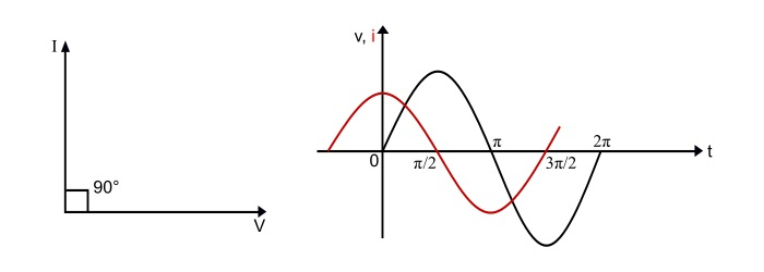
Hence, from the equations (1) and (3), it is clear that current leads the applied voltage by 90°. It can also be represented by the phasor diagram and waveform.
Capacitive Reactance
Since,
$$\mathrm{I_{m}= \omega CV_{m}}$$
$$\mathrm{\Rightarrow \frac{V_{m}}{I_{m}}=\frac{V_{m}/ \sqrt{2}}{I_{m} \sqrt{2}}=\frac{V}{I}=\frac{1}{\omega C}}$$
$$\mathrm{X_{c}=\frac{1}{\omega C}=\frac{1}{2 \pi fc}}\:\:\:… (4)$$

Where,
V and I are the r.m.s. values of voltage and current respectively.
f is the supply frequency in Hz.
The ω = 2πf is the angular frequency of the supply measured in rad/sec.
Therefore, the opposition offered by the capacitor to flow of current is XC. It is known as capacitive reactance of the capacitor. The XC is measured in ohms(Ω).
Power
Instantaneous power − It is the product of instantaneous voltage and instantaneous current. It is denoted by lower case letter p, i.e.
$$\mathrm{p=\nu i=V_{m}sin(\omega t)× I_{m}sin(\omega t + 90^{\circ})}$$
$$\mathrm{\Rightarrow p=V_{m} I_{m}sin(\omega t)\:cos(\omega t)=\frac{V_{m} I_{m}}{2}sin(2\omega t)}\:\:\:\:… (5)$$
Average Power − The average power is the mean of instantaneous power over a complete cycle and denoted by upper case letter P, hence,
$$\mathrm{p = Average\:of\:over\:one\:cycle}$$
$$\mathrm{p=\frac{1}{2\pi}\int_{0}^{2\pi}sin(2\omega t)d (\omega t)=0}$$
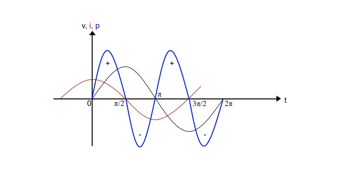
Thus, the average power absorbed in a pure capacitor is zero over one complete cycle. From the power curve, it is clear that the positive power is equal to the negative power over one cycle. Therefore, the net power absorbed in a pure capacitor is zero.
Numerical Example
A 250 V, 50Hz voltage is applied across a pure capacitor of 400 µF capacitance. Determine following −
- Capacitive reactance
- RMS value of circuit current
- Equation for voltage and current.
Solution
- Capacitive reactance
$$\mathrm{X_{c}=\frac{1}{2\pi fC}=\frac{1}{2\pi × 50 × 400 × 10−6}=7.962 Ω}$$
- RMS value of circuit current
$$\mathrm{I=\frac{V}{X_{c}}=\frac{250}{7.962}=31.39 A}$$
- Equations for the voltage and current
$$\mathrm{Maximum\:value\:of\:voltage,V_{m}= √2×V= √2 × 250 = 353.5 V}$$
$$\mathrm{Maximum\:value\:of\:current,I_{m}= √2 ×I= √2 × 31.39 = 44.39 A}$$
$$\mathrm{Angular\:frequency,\omega = 2\pi f= 2\pi× 50 = 314 rad⁄sec}$$
Therefore,
$$\mathrm{Equation\:for\:voltage,\nu=V_{m}sin(\omega t) = 353.5 sin 314t}$$
$$\mathrm{Equation for current,i=I_{m}sin(\omega t + 90°) = 44.39 sin(314? + 90°)}$$

2K+ Views
