- Electrical Machines Tutorial
- Electrical Machines - Home
- Basic Concepts
- Electromechanical Energy Conversion
- Energy Stored in a Magnetic Field
- Singly-Excited and Doubly Excited Systems
- Rotating Electrical Machines
- Faraday’s Laws of Electromagnetic Induction
- Concept of Induced EMF
- Fleming’s Left Hand and Right Hand Rules
- Transformers
- Electrical Transformer
- Construction of Transformer
- EMF Equation of Transformer
- Turns Ratio and Voltage Transformation Ratio
- Ideal and Practical Transformers
- Transformer on DC
- Losses in a Transformer
- Efficiency of Transformer
- Three-Phase Transformer
- Types of Transformers
- DC Machines
- Construction of DC Machines
- Types of DC Machines
- Working Principle of DC Generator
- EMF Equation of DC Generator
- Types of DC Generators
- Working Principle of DC Motor
- Back EMF in DC Motor
- Types of DC Motors
- Losses in DC Machines
- Applications of DC Machines
- Induction Motors
- Introduction to Induction Motor
- Single-Phase Induction Motor
- Three-Phase Induction Motor
- Construction of Three-Phase Induction Motor
- Three-Phase Induction Motor on Load
- Characteristics of 3-Phase Induction Motor
- Speed Regulation and Speed Control
- Methods of Starting 3-Phase Induction Motors
- Synchronous Machines
- Introduction to 3-Phase Synchronous Machines
- Construction of Synchronous Machine
- Working of 3-Phase Alternator
- Armature Reaction in Synchronous Machines
- Output Power of 3-Phase Alternator
- Losses and Efficiency of 3-Phase Alternator
- Working of 3-Phase Synchronous Motor
- Equivalent Circuit and Power Factor of Synchronous Motor
- Power Developed by Synchronous Motor
- Electrical Machines Resources
- Electrical Machines - Quick Guide
- Electrical Machines - Resources
- Electrical Machines - Discussion
Working of 3-Phase Alternator
A 3-phase alternator is a synchronous machine that converts mechanical energy into 3-phase electrical energy through the process of electromagnetic induction.
As we discussed in previous chapters, a 3-phase alternator, also called a 3-phase synchronous generator, has a stationary armature and a rotating magnetic field. In the three-phase alternator, the rotor winding (serves as field winding) is energized from a DC supply and alternate north and south poles are developed on the rotor.
Operation of Three-Phase Alternator
When the rotor is rotated (say in anticlockwise direction) by a prime mover (engine, turbine, etc.), the stator winding (serves as armature winding) is cut by the magnetic flux of the rotor poles. Due to electromagnetic induction, an EMF is induced in the armature winding. This induced EMF is alternating one because the north and south poles of the rotor alternately pass the armature winding conductors. We can determine the direction of the induced EMF by Fleming’s right hand rule.
The electrical equivalent circuit of a star-connected armature winding and dc field winding three-phase alternator is shown in Figure-1.
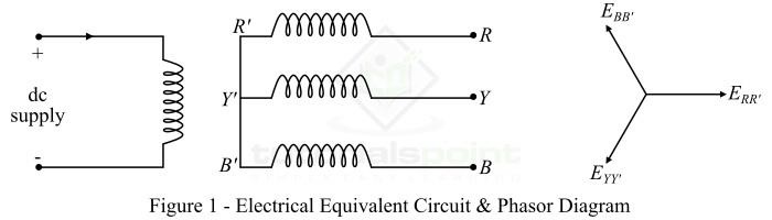
When the rotor is rotated a three-phase voltage is generated in the armature winding. The magnitude of generated voltage depends upon the speed of the rotation of rotor and the DC excitation current. However, the magnitude of generated voltage in each phase of the armature is the same, but displaced by 120° electrical from each other in space as shown in the phasor diagram.
Frequency of Generated Voltage
In a three-phase alternator, the frequency of generated voltage depends upon the speed of rotation and the number of field poles in machine.
Let
N = speed of rotation in RPM
P = number of field poles
Then, the frequency of generated voltage is given by,
$$\mathrm{\mathit{f}\:=\:\frac{\mathit{NP}}{120}\:\mathrm{Hz}\:\cdot \cdot \cdot (1)}$$
It should be noted that N is the synchronous speed because the alternator is a synchronous machine whose rotor always rotates at the synchronous speed.
EMF Equation of Three-Phase Alternator
The mathematical relation which gives the value of EMF induced in the armature winding of a three-phase alternator is termed as its EMF equation.
Let
N = speed of rotation in RPM
P = number of field poles on rotor
$\phi$ = flux per pole in weber
Z = number of armature conductors per phase
Then, in one revolution, each stator conductor is cut by a flux of $\mathit{P\phi }$ Weber, i.e.,
$$\mathrm{\mathit{d\phi }\:=\:\mathit{P\phi }}$$
Also, time taken to complete one revolution is,
$$\mathrm{\mathit{dt }\:=\:\frac{60}{\mathit{N}}}$$
Therefore, the average EMF induced in each armature conductor is,
$$\mathrm{\mathrm{EMF \:per\:conductor}\:=\:\mathit{\frac{d\phi }{dt}}\:=\:\frac{\mathit{P\phi }}{(60/\mathit{N})}\:=\:\frac{\mathit{P\phi N}}{\mathrm{60}}}$$
Since Z is the total number of conductors in the armature winding per phase, then
$$\mathrm{\mathrm{Avg.\:EMF\:per\:phase, }\mathit{E_{av}/\mathrm{phase}}\:=\:\mathit{Z\times }\frac{\mathit{P\phi N}}{\mathrm{60}}}$$
$$\mathrm{\because \mathit{N}\:=\:\frac{120\mathit{f}}{\mathit{P}}}$$
Then,
$$\mathrm{\mathit{E_{av}/}\mathrm{phase}\:=\:\frac{\mathit{P\phi Z}}{60}\times \frac{120\mathit{f}}{\mathit{P}}\:=\:2\mathit{f\phi Z}\:\mathrm{Volts}}$$
Now, the RMS value of generated EMF per phase is given by,
$$\mathrm{\mathit{E_{\mathrm{RMS}}/}\mathrm{phase}\:=\:\left ( \mathit{E_{av}/\mathrm{phase}} \right )\times \mathrm{form\:factor}}$$
In practice, we consider that a three-phase alternator generates a sinusoidal voltage, whose form factor is 1.11.
$$\mathrm{\mathit{E_{\mathrm{RMS}}/}\mathrm{phase}\:=\:2\mathit{f\phi Z}\times 1.11}$$
$$\mathrm{\therefore \mathit{E_{\mathrm{RMS}}/}\mathrm{phase}\:=\:2.22\mathit{f\phi Z}\:\mathrm{volts}\:\cdot \cdot \cdot (2)}$$
Sometimes, number of turns (T) per phase rather than number of conductors per phase are specified. In that case, we have,
$$\mathrm{\mathit{Z}\:=\:2\mathit{T}}$$
$$\mathrm{\therefore \mathit{E_{\mathrm{RMS}}/}\mathrm{phase}\:=\:\mathit{E_{ph}}\:=\:4.44\mathit{f\phi Z}\:\mathrm{volts}\:\cdot \cdot \cdot (3)}$$
The expressions in equations (2) & (3) are known as EMF equation of three-phase alternator.
Numerical Example (1)
What is the frequency of the voltage generated by a three-phase alternator having 6 poles and rotating at 1200 RPM?
Solution
Given data,
P = 6;
N = 1200 RPM
$$\mathrm{\mathrm{Frequency,}\mathit{f}\:=\:\frac{\mathit{NP}}{120}\:=\:\frac{1200\times 6}{120}}$$
$$\mathrm{\therefore\mathit{f} \:=\:60\:Hz}$$
Numerical Example (2)
The armature of a 4-pole, 3-phase, 50 Hz alternator has 24 slots and 10 conductors per slot. A flux of 0.03 Wb is entering the armature from one pole. Calculate the induced EMF per phase.
Solution
$$\mathrm{\mathrm{Total\:number\:of\:conductors}\:=\:24\times 10\:=\:240}$$
$$\mathrm{\mathrm{Number\:of\:conductors\:per\:phase,}\mathit{Z}\:=\:\frac{240}{3}\:=\:80}$$
$$\mathrm{\therefore \mathit{E_{ph}}\:=\:2.22\mathit{f\phi Z}\:=\:2.22\times 50\times 0.03\times 80}$$
$$\mathrm{\mathit{E_{ph}}\:=\:266.4\:V}$$
To Continue Learning Please Login