- Electrical Machines Tutorial
- Electrical Machines - Home
- Basic Concepts
- Electromechanical Energy Conversion
- Energy Stored in a Magnetic Field
- Singly-Excited and Doubly Excited Systems
- Rotating Electrical Machines
- Faraday’s Laws of Electromagnetic Induction
- Concept of Induced EMF
- Fleming’s Left Hand and Right Hand Rules
- Transformers
- Electrical Transformer
- Construction of Transformer
- EMF Equation of Transformer
- Turns Ratio and Voltage Transformation Ratio
- Ideal and Practical Transformers
- Transformer on DC
- Losses in a Transformer
- Efficiency of Transformer
- Three-Phase Transformer
- Types of Transformers
- DC Machines
- Construction of DC Machines
- Types of DC Machines
- Working Principle of DC Generator
- EMF Equation of DC Generator
- Types of DC Generators
- Working Principle of DC Motor
- Back EMF in DC Motor
- Types of DC Motors
- Losses in DC Machines
- Applications of DC Machines
- Induction Motors
- Introduction to Induction Motor
- Single-Phase Induction Motor
- Three-Phase Induction Motor
- Construction of Three-Phase Induction Motor
- Three-Phase Induction Motor on Load
- Characteristics of 3-Phase Induction Motor
- Speed Regulation and Speed Control
- Methods of Starting 3-Phase Induction Motors
- Synchronous Machines
- Introduction to 3-Phase Synchronous Machines
- Construction of Synchronous Machine
- Working of 3-Phase Alternator
- Armature Reaction in Synchronous Machines
- Output Power of 3-Phase Alternator
- Losses and Efficiency of 3-Phase Alternator
- Working of 3-Phase Synchronous Motor
- Equivalent Circuit and Power Factor of Synchronous Motor
- Power Developed by Synchronous Motor
- Electrical Machines Resources
- Electrical Machines - Quick Guide
- Electrical Machines - Resources
- Electrical Machines - Discussion
Types of DC Generators
In practical DC generators, the magnetic field is produced by electromagnets rather than permanent magnets. The DC generators are then classified based on the connection of field winding in the generator circuit. On this basis, DC generators are classified into the following two types −
Separately Excited DC Generators
Self-Excited DC Generators
Separately Excited DC Generator
A DC generator whose magnetic field winding is excited from an independent source of DC electric supply like battery is called a separately excited DC generator. Figure-1 shows the connection diagram of a separately excited DC generator.
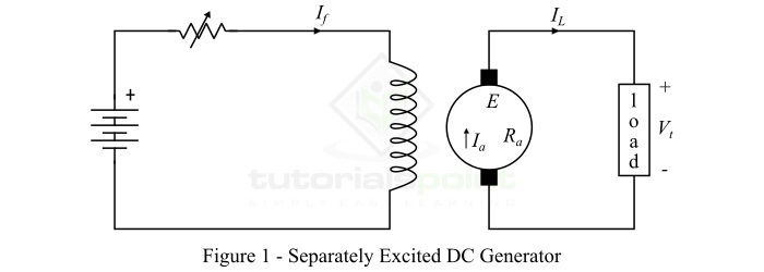
The voltage generated by a separately excited DC generator depends upon the speed of the armature rotation and the field current (i.e. flux in the machine). The greater the speed of armature and field current, greater is the induced EMF in the generator. However, the separately excited DC generators are rarely used in practical applications because these require an external source of DC power for field excitation.
Self-Excited DC Generators
The type of DC generator whose magnetic field winding is excited from the output of the generator itself is known as a self-excited DC generator. Depending upon the manner in which the field winding is connected to the armature, self-excited DC generators are classified into the following three types −
Series DC generator
Shunt DC generator
Compound DC generator
Series DC Generator
A dc generator whose field winding is connected in series with the armature so that whole armature current flows through the field winding as well as the load is called a series DC generator. Figure-2 shows the connection diagram of a series DC generator.
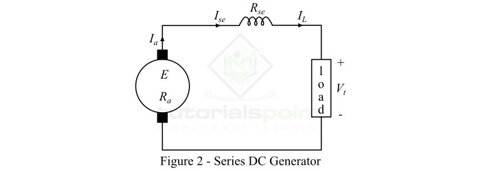
In case of series dc generator, the field winding carries the whole load current, thus it is made up of thick wire with a few turns, so it possesses minimum resistance. The series DC generator is used in special applications like boosters, etc.
The following are some important expressions for the series DC generator −
$$\mathrm{\mathrm{Armature\:current},\mathit{I_{a}}\:=\:\mathit{I_{se}}\:=\:\mathit{I_{L}}}$$
Where,$\mathit{I_{se}}$ is the series field current and $\mathit{I_{L}}$ is the load current.
$$\mathrm{\mathrm{Terminal\:voltage},\mathit{V_{t}}\:=\:\mathit{E-I_{a}\left ( \mathit{R_{a}+R_{se}} \right )}}$$
Where, E is the generated EMF, $\mathit{R_{a}}$ is the armature circuit resistance,$\mathit{R_{se}}$ is the series field resistance.
Shunt DC Generator
A DC generator whose field winding is connected in parallel with the armature winding so that terminal voltage of the generator is applied across it, is known as a shunt DC generator. Figure-3 shows the connection diagram of a shunt DC generator.
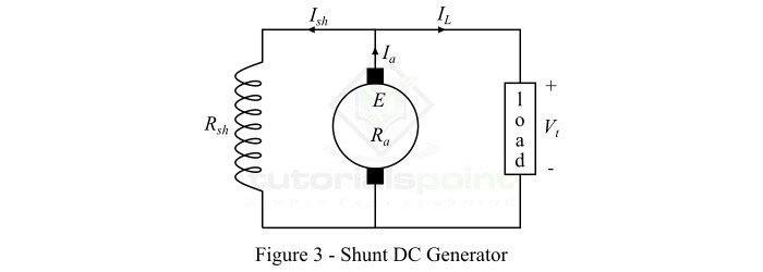
In a shunt DC generator, the shunt field winding has a large number of turns of thin wire so it has high resistance, and therefore only a part of armature current flows through it and the rest flows through the load.
The following are important expressions of a shunt DC generator −
$$\mathrm{\mathrm{Armature\:current,}\mathit{I_{a}}\:=\:\mathit{I_{L}+I_{sh}}}$$
$$\mathrm{\mathrm{Shunt\:field\:current,}\mathit{I_{sh}}\:=\:\frac{\mathit{V_{t}}}{\mathit{R_{sh}}}}$$
$$\mathrm{\mathrm{Terminal\:voltage},\mathit{V_{t}}\:=\:\mathit{E-I_{a}R_{a}}}$$
Compound DC Generator
A compound dc generator is one which has two sets of field windings on each magnetic pole – one is in series and the other is in parallel with the armature winding. The compound dc generators may further be divided into the following two types −
Short-shunt compound DC generator
Long-shunt compound DC generator
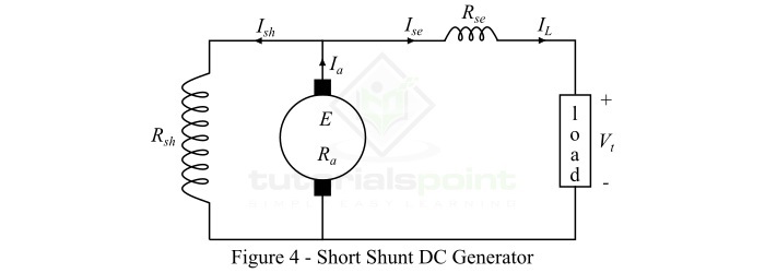
A short-shunt compound DC generator is one in which only shunt field winding is in parallel with the armature winding as shown in Figure-4.
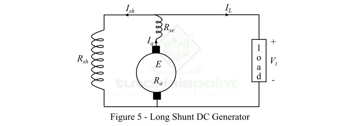
A long-shunt compound DC generator is one in which shunt field winding is in parallel with both series field winding and armature winding as shown in Figure-5.
The following are important expressions for compound DC generators −
For short-shunt generator,
$$\mathrm{\mathrm{Armature\:current,}\mathit{I_{a}}\:=\:\mathit{I_{L}+I_{sh}}}$$
$$\mathrm{\mathrm{Series\:field\:current,}\mathit{I_{se}}\:=\:\mathit{I_{L}}}$$
$$\mathrm{\mathrm{Shunt\:field\:current,}\mathit{I_{sh}}\:=\:\frac{\mathit{V_{t}}+\mathit{I_{se}R_{se}}}{R_{sh}}}$$
$$\mathrm{\mathrm{Terminal\:voltage},\mathit{V_{t}}\:=\:\mathit{E-I_{a}R_{a}-I_{se}R_{se}}}$$
For long-shunt generator,
$$\mathrm{\mathrm{Armature\:current,}\mathit{I_{a}}\:=\:\mathit{I_{L}+I_{sh}}}$$
$$\mathrm{\mathrm{Series\:field\:current,}\mathit{I_{se}}\:=\:\mathit{I_{a}}}$$
$$\mathrm{\mathrm{Shunt\:field\:current,}\mathit{I_{sh}}\:=\:\frac{\mathit{V_{t}}}{\mathit{R_{sh}}}}$$
$$\mathrm{\mathrm{Terminal\:voltage},\mathit{V_{t}}\:=\:\mathit{E-I_{a}}\left ( \mathit{R_{a}+R_{se}} \right )}$$
To Continue Learning Please Login