- Amplifiers Tutorial
- Amplifiers - Home
- Materials - Introduction
- Transistors
- Transistors - Overview
- Transistor Configurations
- Transistor Regions of Operation
- Transistor Load Line Analysis
- Operating Point
- Transistor as an Amplifier
- Transistor Biasing
- Methods of Transistor Biasing
- Bias Compensation
- Amplifiers
- Basic Amplifier
- Classification of Amplifiers
- Based on Configurations
- Multi-Stage Transistor Amplifier
- RC Coupling Amplifier
- Transformer Coupled Amplifier
- Direct Coupled Amplifier
- Power Amplifiers
- Classification of Power Amplifiers
- Class A Power Amplifiers
- Transformer Coupled Class A Power Amplifier
- Push-Pull Class A Power Amplifier
- Class B Power Amplifier
- Class AB and C Power Amplifiers
- Tuned Amplifiers
- Types of Tuned Amplifiers
- Feedback Amplifiers
- Negative Feedback Amplifiers
- Emitter Follower & Darlington Amplifier
- Noise in Amplifiers
- Amplifiers Useful Resources
- Amplifiers - Quick Guide
- Amplifiers - Useful Resources
- Amplifiers - Discussion
Emitter Follower & Darlington Amplifier
Emitter follower and darlington amplifier are the most common examples for feedback amplifiers. These are the mostly used ones with a number of applications.
Emitter Follower
Emitter follower circuit has a prominent place in feedback amplifiers. Emitter follower is a case of negative current feedback circuit. This is mostly used as a last stage amplifier in signal generator circuits.
The important features of Emitter Follower are −
- It has high input impedance
- It has low output impedance
- It is ideal circuit for impedance matching
All these ideal features allow many applications for the emitter follower circuit. This is a current amplifier circuit that has no voltage gain.
Construction
The constructional details of an emitter follower circuit are nearly similar to a normal amplifier. The main difference is that the load RL is absent at the collector terminal, but present at the emitter terminal of the circuit. Thus the output is taken from the emitter terminal instead of collector terminal.
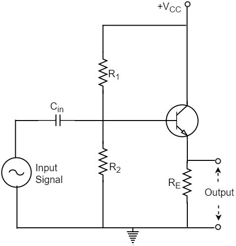
The biasing is provided either by base resistor method or by potential divider method. The following figure shows the circuit diagram of an Emitter Follower.
Operation
The input signal voltage applied between base and emitter, develops an output voltage Vo across RE, which is in the emitter section. Therefore,
$$V_o = I_E R_E$$
The whole of this output current is applied to the input through feedback. Hence,
$$V_f = V_o$$
As the output voltage developed across RL is proportional to the emitter current, this emitter follower circuit is a current feedback circuit. Hence,
$$\beta = \frac{V_f}{V_o} = 1$$
It is also noted that the input signal voltage to the transistor (= Vi) is equal to the difference of Vs and Vo i.e.,
$$V_i = V_s - V_o$$
Hence the feedback is negative.
Characteristics
The major characteristics of the emitter follower are as follows −
- No voltage gain. In fact, the voltage gain is nearly 1.
- Relatively high current gain and power gain.
- High input impedance and low output impedance.
- Input and output ac voltages are in phase.
Voltage Gain of Emitter Follower
As the Emitter Follower circuit is a prominent one, let us try to get the equation for the voltage gain of an emitter follower circuit. Our Emitter Follower circuit looks as follows −
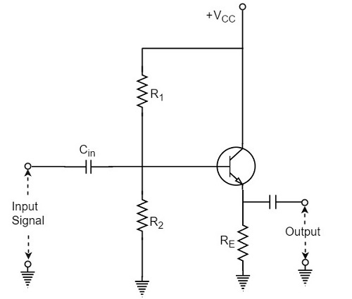
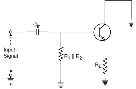
If an AC equivalent circuit of the above circuit is drawn, it would look like the below one, as the emitter by pass capacitor is absent.
The AC resistance rE of the emitter circuit is given by
$$r_E = r’_E + R_E$$
Where
$$r’_E = \frac{25 mV}{I_E}$$
In order to find the voltage gain of the amplifier, the above figure can be replaced by the following figure.
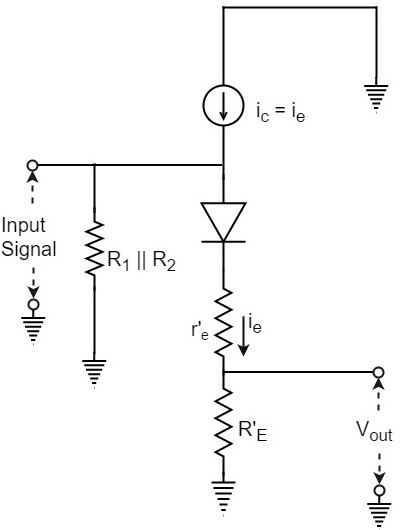
Note that input voltage is applied across the ac resistance of the emitter circuit i.e., (r’E + RE). Assuming the emitter diode to be ideal, the output voltage Vout will be
$$V_{out} = i_e R_E$$
Input voltage Vin will be
$$V_{in} = i_e(r’_e + R_E)$$
Therefore, the Voltage Gain of emitter follower is
$$A_V = \frac{V_{out}}{V_{in}} = \frac{i_e R_E}{i_e(r’_e + R_E)} = \frac{R_E}{(r’_e + R_E)}$$
Or
$$A_V = \frac{R_E}{(r’_e + R_E)}$$
In most practical applications,
$$R_E \gg r’_e$$
So, AV ≈ 1. In practice, the voltage gain of an emitter follower is between 0.8 and 0.999.
Darlington Amplifier
The emitter follower circuit which was just discussed lacks to meet the requirements of the circuit current gain (Ai) and the input impedance (Zi). In order to achieve some increase in the overall values of circuit current gain and input impedance, two transistors are connected as shown in the following circuit diagram, which is known as Darlington configuration.
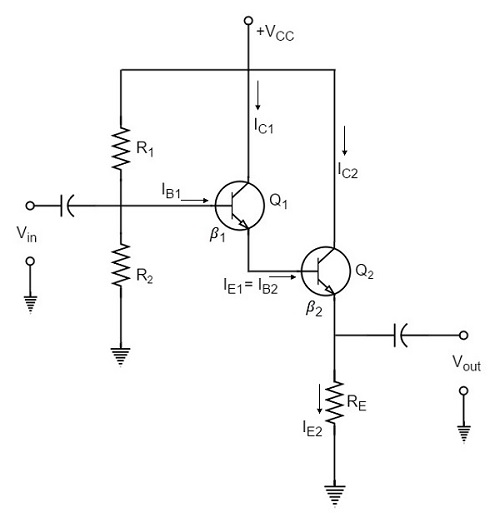
As shown in the above figure, the emitter of the first transistor is connected to the base of the second transistor. The collector terminals of both the transistors are connected together.
Biasing Analysis
Because of this type of connection, the emitter current of the first transistor will also be the base current of the second transistor. Therefore, the current gain of the pair is equal to the product of individual current gains i.e.,
$$\beta = \beta _1 \beta _2$$
A high current gain is generally achieved with a minimum number of components.
As two transistors are used here, two VBE drops are to be considered. The biasing analysis is otherwise similar for one transistor.
Voltage across R2,
$$V_2 = \frac{V_CC}{R_1 + R_2} \times R_2$$
Voltage across RE,
$$V_E = V_2 - 2 V_{BE}$$
Current through RE,
$$I_{E2} = \frac{V_2 - 2 V_{BE}}{R_E}$$
Since the transistors are directly coupled,
$$I_{E1} = I_{B2}$$
Now
$$I_{B2} = \frac{I_{E2}}{\beta _2}$$
Therefore
$$I_{E1} = \frac{I_{E2}}{\beta _2}$$
Which means
$$I_{E1} = I_{E1} \beta _2$$
We have
$I_{E1} = \beta _1 I_{B1}$ since $I_{E1} \cong I_{C1}$
Hence, as
$$I_{E2} = I_{E1} \beta _2$$
We can write
$$I_{E2} = \beta _1 \beta _2 I_{B1}$$
Therefore, Current Gain can be given as
$$\beta = \frac{I_{E2}}{I_{B1}} = \frac{\beta _1 \beta _2 I_{B1}}{I_{B1}} = \beta _1 \beta_2$$
Input impedance of the darling ton amplifier is
$Z_{in} = \beta_1 \beta_2 R_E .....$ neglecting r’e
In practice, these two transistors are placed in a single transistor housing and the three terminals are taken out of the housing as shown in the following figure.
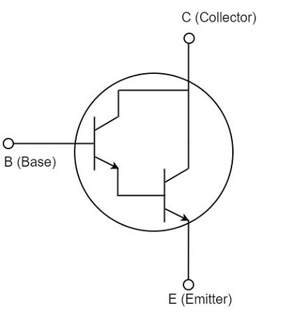
This three terminal device can be called as Darling ton transistor. The darling ton transistor acts like a single transistor that has high current gain and high input impedance.
Characteristics
The following are the important characteristics of Darling ton amplifier.
- Extremely high input impedance (MΩ).
- Extremely high current gain (several thousands).
- Extremely low output impedance (a few Ω).
Since the characteristics of the Darling ton amplifier are basically the same as those of the emitter follower, the two circuits are used for similar applications.
Till now we have discussed amplifiers based on positive feedback. The negative feedback in transistor circuits is helpful in the working of oscillators. The topic of oscillators is entirely covered in Oscillators tutorial.