
Article Categories
- All Categories
-
 Data Structure
-
 Networking
-
 RDBMS
RDBMS
-
 Operating System
-
 Java
Java
-
 MS Excel
-
 iOS
iOS
-
 HTML
HTML
-
 CSS
CSS
-
 Android
-
 Python
-
 C Programming
-
 C++
C++
-
 C#
C#
-
 MongoDB
-
 MySQL
MySQL
-
 Javascript
-
 PHP
PHP
-
 Economics & Finance
What is Instruction Mapping in Computer Architecture?
A unique type of branch exists when a microinstruction defines a branch to the first word in control memory where a micro-program routine for instruction is placed. The status bits for this type of branch are the bits in the operation code part of the instruction. For example, a computer with a simple instruction format as shown in the figure.
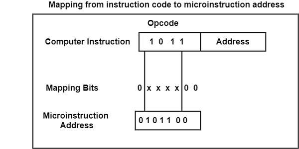
It has an operation code of four bits which can specify up to 16 distinct instructions. It can consider that the control memory has 128 words, needing an address of seven bits. For each operation code, there exists a micro-program routine in control memory that executes the instruction. The mapping procedure converts the 4-bit operation code to a 7-bit address for control memory.
This mapping consists of placing a 0 in the most significant bit of the address, transferring the four operation code bits, and clearing the two least significant bits of the control address register. This provides for each computer instruction a micro-program routine with a capacity of four microinstructions.
If the routine needs more than four microinstructions, it can use addresses 1000000 through 1111111. If it uses fewer than four microinstructions, the unused memory locations would be available for other routines.
One can extend this concept to a more general mapping rule by using a ROM to specifies the mapping function. In this configuration, the bits of the instruction specifies the address of a mapping ROM.
The contents of the mapping ROM give the bits for the control address register. In this way, the micro-program routine that executes the instruction can be placed in any desired location in the control memory. The mapping concept provides flexibility for adding instructions for control memory as the need arises.
The mapping function is sometimes implemented through an integrated circuit called programmable logic device or PLD. A PLD is similar to ROM in concept except that it uses AND and OR gates with internal electronic fuses.
The interconnection between inputs, AND gates, OR gates, and outputs can be programmed as in ROM. A mapping function that can be expressed in terms of Boolean expressions can be implemented conveniently with a PLD.

5K+ Views
