- Satellite Communication - Home
- Introduction
- Orbital Mechanics
- Kepler’s Laws
- Earth Orbit Satellites
- Look Angles & Orbital Perturbations
- Launching
- Subsystems
- AOC Subsystem
- TTCM Subsystem
- Power & Antenna Subsystems
- Transponders
- Earth Segment Subsystems
- Examples of Earth Stations
- Link Budget
- Multiple Access Techniques
- Satellite Services
- Global Positioning System
Satellite Communication - Quick Guide
Satellite Communication - Introduction
In general terms, a satellite is a smaller object that revolves around a larger object in space. For example, moon is a natural satellite of earth.
We know that Communication refers to the exchange (sharing) of information between two or more entities, through any medium or channel. In other words, it is nothing but sending, receiving and processing of information.
If the communication takes place between any two earth stations through a satellite, then it is called as satellite communication. In this communication, electromagnetic waves are used as carrier signals. These signals carry the information such as voice, audio, video or any other data between ground and space and vice-versa.
Soviet Union had launched the world's first artificial satellite named, Sputnik 1 in 1957. Nearly after 18 years, India also launched the artificial satellite named, Aryabhata in 1975.
Need of Satellite Communication
The following two kinds of propagation are used earlier for communication up to some distance.
Ground wave propagation − Ground wave propagation is suitable for frequencies up to 30MHz. This method of communication makes use of the troposphere conditions of the earth.
Sky wave propagation − The suitable bandwidth for this type of communication is broadly between 3040 MHz and it makes use of the ionosphere properties of the earth.
The maximum hop or the station distance is limited to 1500KM only in both ground wave propagation and sky wave propagation. Satellite communication overcomes this limitation. In this method, satellites provide communication for long distances, which is well beyond the line of sight.
Since the satellites locate at certain height above earth, the communication takes place between any two earth stations easily via satellite. So, it overcomes the limitation of communication between two earth stations due to earths curvature.
How a Satellite Works
A satellite is a body that moves around another body in a particular path. A communication satellite is nothing but a microwave repeater station in space. It is helpful in telecommunications, radio and television along with internet applications.
A repeater is a circuit, which increases the strength of the received signal and then transmits it. But, this repeater works as a transponder. That means, it changes the frequency band of the transmitted signal from the received one.
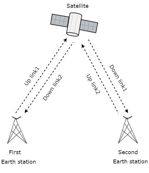
The frequency with which, the signal is sent into the space is called as Uplink frequency. Similarly, the frequency with which, the signal is sent by the transponder is called as Downlink frequency. The following figure illustrates this concept clearly.
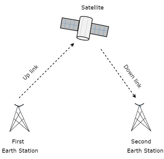
The transmission of signal from first earth station to satellite through a channel is called as uplink. Similarly, the transmission of signal from satellite to second earth station through a channel is called as downlink.
Uplink frequency is the frequency at which, the first earth station is communicating with satellite. The satellite transponder converts this signal into another frequency and sends it down to the second earth station. This frequency is called as Downlink frequency. In similar way, second earth station can also communicate with the first one.
The process of satellite communication begins at an earth station. Here, an installation is designed to transmit and receive signals from a satellite in an orbit around the earth. Earth stations send the information to satellites in the form of high powered, high frequency (GHz range) signals.
The satellites receive and retransmit the signals back to earth where they are received by other earth stations in the coverage area of the satellite. Satellite's footprint is the area which receives a signal of useful strength from the satellite.
Pros and Cons of Satellite Communication
In this section, let us have a look at the advantages and disadvantages of satellite communication.
Following are the advantages of using satellite communication:
Area of coverage is more than that of terrestrial systems
Each and every corner of the earth can be covered
Transmission cost is independent of coverage area
More bandwidth and broadcasting possibilites
Following are the disadvantages of using satellite communication −
Launching of satellites into orbits is a costly process.
Propagation delay of satellite systems is more than that of conventional terrestrial systems.
Difficult to provide repairing activities if any problem occurs in a satellite system.
Free space loss is more
There can be congestion of frequencies.
Applications of Satellite Communication
Satellite communication plays a vital role in our daily life. Following are the applications of satellite communication −
Radio broadcasting and voice communications
TV broadcasting such as Direct To Home (DTH)
Internet applications such as providing Internet connection for data transfer, GPS applications, Internet surfing, etc.
Military applications and navigations
Remote sensing applications
Weather condition monitoring & Forecasting
Satellite Communication - Orbital Mechanics
We know that the path of satellite revolving around the earth is known as orbit. This path can be represented with mathematical notations. Orbital mechanics is the study of the motion of the satellites that are present in orbits. So, we can easily understand the space operations with the knowledge of orbital motion.
Orbital Elements
Orbital elements are the parameters, which are helpful for describing the orbital motion of satellites. Following are the orbital elements.
- Semi major axis
- Eccentricity
- Mean anomaly
- Argument of perigee
- Inclination
- Right ascension of ascending node
The above six orbital elements define the orbit of earth satellites. Therefore, it is easy to discriminate one satellite from other satellites based on the values of orbital elements.
Semi major axis
The length of Semi-major axis (a) defines the size of satellites orbit. It is half of the major axis. This runs from the center through a focus to the edge of the ellipse. So, it is the radius of an orbit at the orbit's two most distant points.
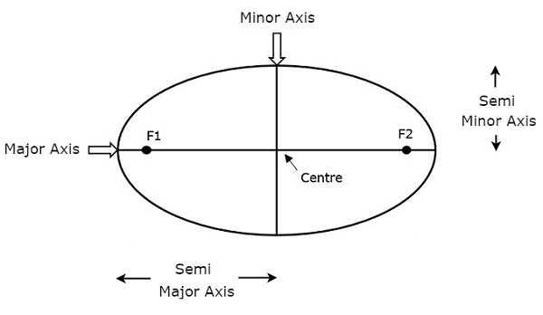
Both semi major axis and semi minor axis are represented in above figure. Length of semi major axis (a) not only determines the size of satellites orbit, but also the time period of revolution.
If circular orbit is considered as a special case, then the length of semi-major axis will be equal to radius of that circular orbit.
Eccentricity
The value of Eccentricity (e) fixes the shape of satellites orbit. This parameter indicates the deviation of the orbits shape from a perfect circle.
If the lengths of semi major axis and semi minor axis of an elliptical orbit are a & b, then the mathematical expression for eccentricity (e) will be
$$e = \frac{\sqrt{a^2 - b^2}}{a}$$
The value of eccentricity of a circular orbit is zero, since both a & b are equal. Whereas, the value of eccentricity of an elliptical orbit lies between zero and one.
The following figure shows the various satellite orbits for different eccentricity (e) values
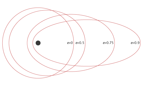
In above figure, the satellite orbit corresponding to eccentricity (e) value of zero is a circular orbit. And, the remaining three satellite orbits are of elliptical corresponding to the eccentricity (e) values 0.5, 0.75 and 0.9.
Mean Anomaly
For a satellite, the point which is closest from the Earth is known as Perigee. Mean anomaly (M) gives the average value of the angular position of the satellite with reference to perigee.
If the orbit is circular, then Mean anomaly gives the angular position of the satellite in the orbit. But, if the orbit is elliptical, then calculation of exact position is very difficult. At that time, Mean anomaly is used as an intermediate step.
Argument of Perigee
Satellite orbit cuts the equatorial plane at two points. First point is called as descending node, where the satellite passes from the northern hemisphere to the southern hemisphere. Second point is called as ascending node, where the satellite passes from the southern hemisphere to the northern hemisphere.
Argument of perigee () is the angle between ascending node and perigee. If both perigee and ascending node are existing at same point, then the argument of perigee will be zero degrees
Argument of perigee is measured in the orbital plane at earths center in the direction of satellite motion.
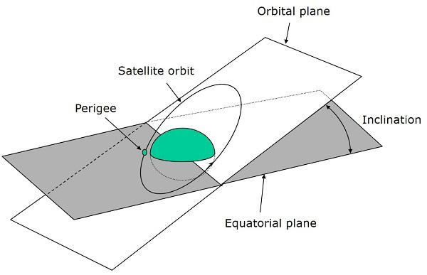
Inclination
The angle between orbital plane and earths equatorial plane is known as inclination (i). It is measured at the ascending node with direction being east to north. So, inclination defines the orientation of the orbit by considering the equator of earth as reference.
There are four types of orbits based on the angle of inclination.
Equatorial orbit − Angle of inclination is either zero degrees or 180 degrees.
Polar orbit − Angle of inclination is 90 degrees.
Prograde orbit − Angle of inclination lies between zero and 90 degrees.
Retrograde orbit − Angle of inclination lies between 90 and 180 degrees.
Right Ascension of Ascending node
We know that ascending node is the point, where the satellite crosses the equatorial plane while going from the southern hemisphere to the northern hemisphere.
Right Ascension of ascending node () is the angle between line of Aries and ascending node towards east direction in equatorial plane. Aries is also called as vernal and equinox.
Satellites ground track is the path on the surface of the Earth, which lies exactly below its orbit. The ground track of a satellite can take a number of different forms depending on the values of the orbital elements.
Orbital Equations
In this section, let us discuss about the equations which are related to orbital motion.
Forces acting on Satellite
A satellite, when it revolves around the earth, it undergoes a pulling force from the earth due to earths gravitational force. This force is known as Centripetal force (F1) because this force tends the satellite towards it.
Mathematically, the Centripetal force (F1) acting on satellite due to earth can be written as
$$F_{1} = \frac{GMm}{R^2} $$
Where,
G is universal gravitational constant and it is equal to 6.673 x 10⁻¹¹ Nm2/kg2.
M is mass of the earth and it is equal to 5.98 x 1024 Kg.
m is mass of the satellite.
R is the distance from satellite to center of the Earth.
A satellite, when it revolves around the earth, it undergoes a pulling force from the sun and the moon due to their gravitational forces. This force is known as Centrifugal force (F2) because this force tends the satellite away from earth.
Mathematically, the Centrifugal force (F2) acting on satellite can be written as
$$F_{2} = \frac{mv^2}{R} $$
Where, v is the orbital velocity of satellite.
Orbital Velocity
Orbital velocity of satellite is the velocity at which, the satellite revolves around earth. Satellite doesnt deviate from its orbit and moves with certain velocity in that orbit, when both Centripetal and Centrifugal forces are balance each other.
So, equate Centripetal force (F1) and Centrifugal force (F2).
$$\frac{GMm}{R^2} = \frac{mv^2}{R}$$
$$= > \frac{GM}{R} = v^2$$
$$= > v = \sqrt{\frac{GM}{R}}$$
Therefore, the orbital velocity of satellite is
$$v = \sqrt{\frac{GM}{R}}$$
Where,
G is gravitational constant and it is equal to 6.673 x 10⁻¹¹ Nm2/kg2.
M is mass of the earth and it is equal to 5.98 x 1024 Kg.
R is the distance from satellite to center of the Earth.
So, the orbital velocity mainly depends on the distance from satellite to center of the Earth (R), since G & M are constants.
Satellite Communication - Keplers Laws
We know that satellite revolves around the earth, which is similar to the earth revolves around the sun. So, the principles which are applied to earth and its movement around the sun are also applicable to satellite and its movement around the earth.
Many scientists have given different types of theories from early times. But, only Johannes Kepler (1571-1630) was one of the most accepted scientist in describing the principle of a satellite that moves around the earth.
Kepler formulated three laws that changed the whole satellite communication theory and observations. These are popularly known as Keplers laws. These are helpful to visualize the motion through space.
Keplers First Law
Keplers first law states that the path followed by a satellite around its primary (the earth) will be an ellipse. This ellipse has two focal points (foci) F1 and F2 as shown in the figure below. Center of mass of the earth will always present at one of the two foci of the ellipse.
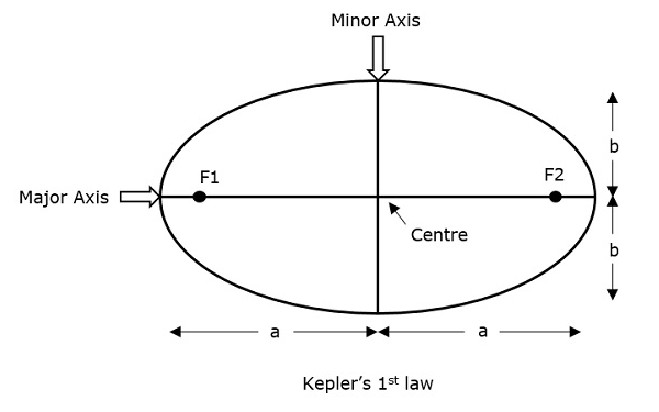
If the distance from the center of the object to a point on its elliptical path is considered, then the farthest point of an ellipse from the center is called as apogee and the shortest point of an ellipse from the center is called as perigee.
Eccentricity "e" of this system can be written as −
$$e = \frac{\sqrt{a^2 - b^2}}{a}$$
Where, a & b are the lengths of semi major axis and semi minor axis of the ellipse respectively.
For an elliptical path, the value of eccentricity (e) is always lie in between 0 and 1, i.e. $0$ < $e$ < $1$, since a is greater than b. Suppose, if the value of eccentricity (e) is zero, then the path will be no more in elliptical shape, rather it will be converted into a circular shape.
Keplers Second Law
Keplers second law states that for equal intervals of time, the area covered by the satellite will be same with respect to center of mass of the earth. This can be understood by taking a look at the following figure.
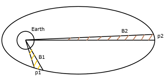
Assume, the satellite covers p1 and p2 distances in the same time interval. Then, the areas B1 and B2 covered by the satellite at those two instances are equal.
Keplers Third Law
Keplers third law states that, the square of the periodic time of an elliptical orbit is proportional to the cube of its semi major axis length. Mathematically, it can be written as follows −
$$T^2\:\alpha\:a^3$$
$$=> T^2=\left(\frac{4\pi ^2}{\mu }\right) a^3$$
Where, $\frac{4\pi^2}{\mu}$ is the proportionality constant.
$\mu$ is Keplers constant and its value is equal to 3.986005 x 10¹⁴m3 /sec2
$$1 = \left(\frac{2\pi}{T}\right)^2\left(\frac{a^2}{\mu}\right)$$
$$1 = n^2\left(\frac{a^3}{\mu}\right)$$
$$=> a^3 = \frac{\mu}{n^2}$$
Where, n is the mean motion of the satellite in radians per second.
Note − A satellite, when it revolves around the earth, undergoes a pulling force from the earth, which is gravitational force. Similarly, it experiences another pulling force from the sun and the moon. Therefore, a satellite has to balance these two forces to keep itself in its orbit.
Earth Orbit Satellites
Satellite should be properly placed in the corresponding orbit after leaving it in the space. It revolves in a particular way and serves its purpose for scientific, military or commercial. The orbits, which are assigned to satellites with respect to earth are called as Earth Orbits. The satellites present in those orbits are called as Earth Orbit Satellites.
We should choose an orbit properly for a satellite based on the requirement. For example, if the satellite is placed in lower orbit, then it takes less time to travel around the earth and there will be better resolution in an onboard camera. Similarly, if the satellite is placed in higher orbit, then it takes more time to travel around the earth and it covers more earths surface at one time.
Following are the three important types of Earth Orbit satellites −
- Geosynchronous Earth Orbit Satellites
- Medium Earth Orbit Satellites
- Low Earth Orbit Satellites
Now, let us discuss about each type of earth orbit satellites one by one.
Geosynchronous Earth OrbitSatellites
A Geo-synchronous Earth Orbit (GEO) Satellite is one, which is placed at an altitude of 22,300 miles above the Earth. This orbit is synchronized with a side real day (i.e., 23 hours 56 minutes). This orbit can have inclination and eccentricity.
It may not be circular. This orbit can be tilted at the poles of the earth. But, it appears stationary when observed from the Earth. These satellites are used for satellite Television.
The same geo-synchronous orbit, if it is circular and in the plane of equator, then it is called as Geostationary orbit. These Satellites are placed at 35,900kms (same as Geosynchronous) above the Earths Equator and they keep on rotating with respect to earths direction (west to east).
The satellites present in these orbits have the angular velocity same as that of earth. Hence, these satellites are considered as stationary with respect to earth since, these are in synchronous with the Earths rotation.
The advantage of Geostationary orbit is that no need to track the antennas in order to find the position of satellites.
Geostationary Earth Orbit Satellites are used for weather forecasting, satellite TV, satellite radio and other types of global communications.
The following figure shows the difference between Geo-synchronous and Geo-stationary orbits. The axis of rotation indicates the movement of Earth.
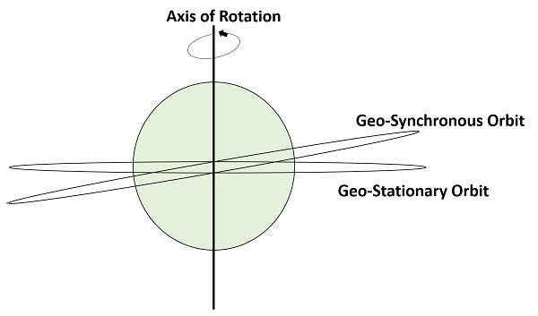
Note − Every Geostationary orbit is a Geo-synchronous orbit. But, the converse need not be true.
Medium Earth Orbit Satellites
Medium Earth Orbit (MEO) satellites will orbit at distances of about 8000 miles from earth's surface. Signals transmitted from a MEO satellite travel a shorter distance. Due to this, the signal strength at the receiving end gets improved. This shows that smaller and light weight receiving terminals can be used at the receiving end.
Transmission delay can be defined as the time it takes for a signal to travel up to a satellite and back down to a receiving station. In this case, there is less transmission delay. Because, the signal travels for a shorter distance to and from the MEO satellite.
For real-time communications, the shorter the transmission delay, the better will be the communication system. As an example, if a GEO satellite requires 0.25 seconds for a round trip, then MEO satellite requires less than 0.1 seconds to complete the same trip. MEOs operate in the frequency range of 2 GHz and above.
These satellites are used for High speed telephone signals. Ten or more MEO satellites are required in order to cover entire earth.
Low Earth Orbit Satellites
Low Earth Orbit LEO) satellites are mainly classified into three categories. Those are little LEOs, big LEOs, and Mega-LEOs. LEOs will orbit at a distance of 500 to 1000 miles above the earth's surface. These satellites are used for satellite phones and GPS.
This relatively short distance reduces transmission delay to only 0.05 seconds. This further reduces the need for sensitive and bulky receiving equipment. Twenty or more LEO satellites are required to cover entire earth.
Little LEOs will operate in the 800 MHz (0.8 GHz) range. Big LEOs will operate in the 2 GHz or above range, and Mega-LEOs operates in the 20-30 GHz range.
The higher frequencies associated with Mega-LEOs translates into more information carrying capacity and yields to the capability of real-time, low delay video transmission scheme.
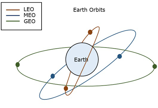
The following figure depicts the paths of LEO, MEO and GEO
Orbital Slots
Here, a question may arise that with more than 200 satellites that are in geosynchronous orbit, how do we keep them from running into each other or from attempting to use the same location in space?
To answer this problem (question), international regulatory bodies like the International Telecommunications Union (ITU) and national government organizations like the Federal Communications Commission (FCC) designate the locations on the geosynchronous orbit, where the communications satellites can be located.
These locations are specified in degrees of longitude and are called as orbital slots. The FCC and ITU have progressively reduced the required spacing down to only 2 degrees for C-band and Ku-band satellites due to the huge demand for orbital slots.
Look Angles & Orbital Perturbations
Earth station will receive the maximum signal level, if it is located directly under the satellite. Otherwise, it wont receive maximum signal level and that signal level decreases as the difference between the latitude and longitude of earth station increases.
So, based on the requirement we can place the satellite in a particular orbit. Now, let us discuss about the look angles.
Look Angles
The following two angles of earth station antenna combined together are called as look angles.
- Azimuth Angle
- Elevation Angle
Generally, the values of these angles change for non-geostationary orbits. Whereas, the values of these angles dont change for geostationary orbits. Because, the satellites present in geostationary orbits appear stationary with respect to earth.
These two angles are helpful in order to point at the satellite directly from the earth station antenna. So, the maximum gain of the earth station antenna can be directed at satellite.
We can calculate the look angles of geostationary orbit by using longitude & latitude of earth station and position of satellite orbit.
Azimuth Angle
The angle between local horizontal plane and the plane passing through earth station, satellite and center of earth is called as azimuth angle.
The formula for Azimuth angle ($\alpha$) is
$$\alpha\: = 180^0 + Tan^{-1}\left(\frac{Tan G}{TanL}\right)$$
Where,
L is Latitude of earth station antenna.
G is the difference between position of satellite orbit and earth station antenna.
The following figure illustrates the azimuth angle.
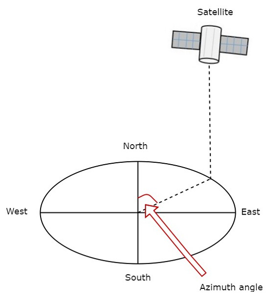
Measure the horizontal angle at earth station antenna to north pole as shown in figure. It represents azimuth angle. It is used to track the satellite horizontally.
Elevation Angle
The angle between vertical plane and line pointing to satellite is known as Elevation angle. Vertical plane is nothing but the plane, which is perpendicular to horizontal plane.
The formula for Elevation angle ($\beta$) is
$$\beta = Tan^{-1}\left(\frac{cosG.cosL-0.15}{\sqrt{1-cos^2G.cos^2L}}\right)$$
We can calculate the elevation angle by using above formula. The following figure illustrates the elevation angle.
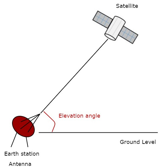
Measure the vertical angle at earth station antenna from ground to satellite as shown in the figure. It represents elevation angle.
Orbital Perturbations
Following are the orbital perturbations due to gravitational and non-gravitational forces or parameters.
Irregular gravitational force around the Earth due to non-uniform mass distribution. Earths magnetic field too causes orbital perturbations.
Main external perturbations come from Sun and Moon. When a satellite is near to these external bodies, it receives a stronger gravitational pull.
Low-orbit satellites get affected due to friction caused by collision with atoms and ions.
Solar radiation pressure affects large GEO satellites, which use large solar arrays.
Self-generated torques and pressures caused by RF radiation from the antenna.
Most satellites use a propulsion subsystem in order to maintain a proper spin axis direction and control the altitude of the satellite against perturbation forces.
Satellite Communication - Launching
Satellites stay in space for most of their life time. We know that the environment of weightlessness is present in the space. Thats why satellites dont require additional strong frames in space. But, those are required during launching process. Because in that process satellite shakes violently, till the satellite has been placed in a proper orbit.
The design of satellites should be compatible with one or more launch vehicles in order to place the satellite in an orbit.
We know that the period of revolution will be more for higher apogee altitude according to Keplers second law. The period of geostationary transfer orbit is nearly equal to 16 hours. If perigee is increased to GEO altitude (around 36,000 km), then the period of revolution will increase to 24 hours.
Launching of Satellites
The process of placing the satellite in a proper orbit is known as launching process. During this process, from earth stations we can control the operation of satellite. Mainly, there are four stages in launching a satellite.
First Stage − The first stage of launch vehicle contains rockets and fuel for lifting the satellite along with launch vehicle from ground.
Second Stage − The second stage of launch vehicle contains smaller rockets. These are ignited after completion of first stage. They have their own fuel tanks in order to send the satellite into space.
Third Stage − The third (upper) stage of the launch vehicle is connected to the satellite fairing. This fairing is a metal shield, which contains the satellite and it protects the satellite.
Fourth Stage − Satellite gets separated from the upper stage of launch vehicle, when it has been reached to out of Earth's atmosphere. Then, the satellite will go to a transfer orbit. This orbit sends the satellite higher into space.
When the satellite reached to the desired height of the orbit, its subsystems like solar panels and communication antennas gets unfurled. Then the satellite takes its position in the orbit with other satellites. Now, the satellite is ready to provide services to the public.
Satellite Launch Vehicles
Satellite launch vehicles launch the satellites into a particular orbit based on the requirement. Satellite launch vehicles are nothing but multi stage rockets. Following are the two types of satellite launch vehicles.
- Expendable Launch Vehicles (ELV)
- Reusable Launch Vehicles (RLV)
Expendable Launch Vehicles
Expendable launch vehicles (ELV) get destroyed after leaving the satellites in space. The following image shows how an ELV looks.
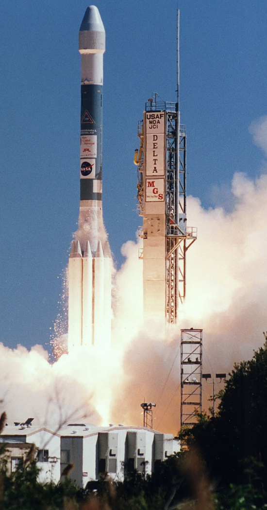
The ELV contains three stages. First and second stages of ELV raise the satellite to an about 50 miles and 100 miles. Third stage of ELV places the satellite in transfer orbit. The task of ELV will be completed and its spare parts will be fallen to earth, when the satellite reached to transfer orbit.
Reusable Launch Vehicles
Reusable launch vehicles (RLV) can be used multiple times for launching satellites. Generally, this type of launch vehicles will return back to earth after leaving the satellite in space.
The following image shows a reusable launch vehicle. It is also known as space shuttle.
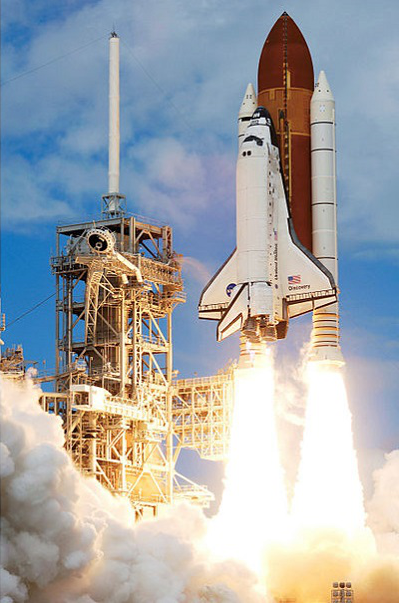
The functions of space shuttle are similar to the functions of first and second stages of ELV. Satellite along with the third stage of space shuttle are mounted in the cargo bay. It is ejected from the cargo bay when the space shuttle reaches to an elevation of 150 to 200 miles.
Then, the third stage of space shuttle gets fired and places the satellite into a transfer orbit. After this, the space shuttle will return back to earth for reuse.
Satellite Communication - Subsystems
In satellite communication system, various operations take place. Among which, the main operations are orbit controlling, altitude of satellite, monitoring and controlling of other subsystems.
A satellite communication consists of mainly two segments. Those are space segment and earth segment. So, accordingly there will be two types of subsystems namely, space segment subsystems and earth segment subsystems. The following figure illustrates this concept.
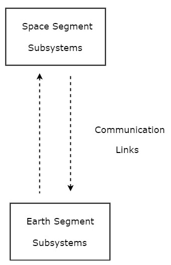
As shown in the figure, the communication takes place between space segment subsystems and earth segment subsystems through communication links.
Space Segment Subsystems
The subsystems present in space segment are called as space segment subsystems. Following are the space segment subsystems.
- AOC Subsystem
- TTCM Subsystem
- Power and Antenna Subsystems
- Transponders
Earth Segment Subsystems
The subsystems present in the ground segment have the ability to access the satellite repeater in order to provide the communication between the users. Earth segment is also called as ground segment.
Earth segment performs mainly two functions. Those are transmission of a signal to the satellite and reception of signal from the satellite. Earth stations are the major subsystems that are present in earth segment.
We will discuss about all these subsystems of space segment and earth segment in following chapters.
Satellite Communication - AOC Subsystem
We know that satellite may deviates from its orbit due to the gravitational forces from sun, moon and other planets. These forces change cyclically over a 24-hour period, since the satellite moves around the earth.
Altitude and Orbit Control (AOC) subsystem consists of rocket motors, which are capable of placing the satellite into the right orbit, whenever it is deviated from the respective orbit. AOC subsystem is helpful in order to make the antennas, which are of narrow beam type points towards earth.
We can make this AOC subsystem into the following two parts.
- Altitude Control Subsystem
- Orbit Control Subsystem
Now, let us discuss about these two subsystems one by one.
Altitude Control Subsystem
Altitude control subsystem takes care of the orientation of satellite in its respective orbit. Following are the two methods to make the satellite that is present in an orbit as stable.
- Spinning the satellite
- Three axes method
Spinning the satellite
In this method, the body of the satellite rotates around its spin axis. In general, it can be rotated at 30 to 100 rpm in order to produce a force, which is of gyroscopic type. Due to this, the spin axis gets stabilized and the satellite will point in the same direction. Satellites are of this type are called as spinners.
Spinner contains a drum, which is of cylindrical shape. This drum is covered with solar cells. Power systems and rockets are present in this drum.
Communication subsystem is placed on top of the drum. An electric motor drives this communication system. The direction of this motor will be opposite to the rotation of satellite body, so that the antennas point towards earth. The satellites, which perform this kind of operation are called as de-spin.
During launching phase, the satellite spins when the small radial gas jets are operated. After this, the de-spin system operates in order to make the TTCM subsystem antennas point towards earth station.
Three Axis Method
In this method, we can stabilize the satellite by using one or more momentum wheels. This method is called as three-axis method. The advantage of this method is that the orientation of the satellite in three axes will be controlled and no need of rotating satellites main body.
In this method, the following three axes are considered.
Roll axis is considered in the direction in which the satellite moves in orbital plane.
Yaw axis is considered in the direction towards earth.
Pitch axis is considered in the direction, which is perpendicular to orbital plane.
These three axes are shown in below figure.
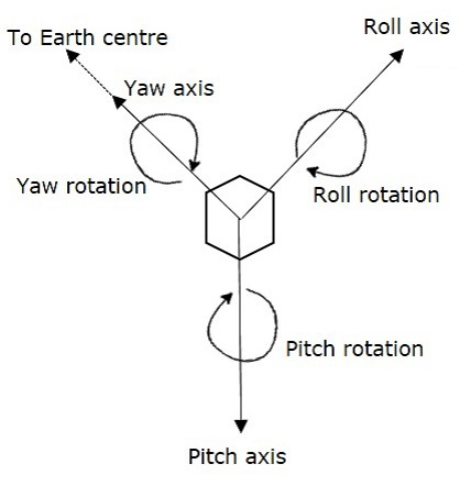
Let XR, YR and ZR are the roll axis, yaw axis and pitch axis respectively. These three axis are defined by considering the satellites position as reference. These three axes define the altitude of satellite.
Let X, Y and Z are another set of Cartesian axes. This set of three axis provides the information about orientation of the satellite with respect to reference axes. If there is a change in altitude of the satellite, then the angles between the respective axes will be changed.
In this method, each axis contains two gas jets. They will provide the rotation in both directions of the three axes.
The first gas jet will be operated for some period of time, when there is a requirement of satellites motion in a particular axis direction.
The second gas jet will be operated for same period of time, when the satellite reaches to the desired position. So, the second gas jet will stop the motion of satellite in that axis direction.
Orbit Control Subsystem
Orbit control subsystem is useful in order to bring the satellite into its correct orbit, whenever the satellite gets deviated from its orbit.
The TTCM subsystem present at earth station monitors the position of satellite. If there is any change in satellite orbit, then it sends a signal regarding the correction to Orbit control subsystem. Then, it will resolve that issue by bringing the satellite into the correct orbit.
In this way, the AOC subsystem takes care of the satellite position in the right orbit and at right altitude during entire life span of the satellite in space.
Satellite Communication - TTCM Subsystem
Telemetry, Tracking, Commanding and Monitoring (TTCM) subsystem is present in both satellite and earth station. In general, satellite gets data through sensors. So, Telemetry subsystem present in the satellite sends this data to earth station(s). Therefore, TTCM subsystem is very much necessary for any communication satellite in order to operate it successfully.
It is the responsibility of satellite operator in order to control the satellite in its life time, after placing it in the proper orbit. This can be done with the help of TTCM subsystem.
We can make this TTCM subsystem into the following three parts.
- Telemetry and Monitoring Subsystem
- Tracking Subsystem
- Commanding Subsystem
Telemetry and Monitoring Subsystem
The word Telemetry means measurement at a distance. Mainly, the following operations take place in Telemetry.
Generation of an electrical signal, which is proportional to the quantity to be measured.
Encoding the electrical signal.
Transmitting this code to a far distance.
Telemetry subsystem present in the satellite performs mainly two functions −
- receiving data from sensors, and
- transmitting that data to an earth station.
Satellites have quite a few sensors to monitor different parameters such as pressure, temperature, status and etc., of various subsystems. In general, the telemetry data is transmitted as FSK or PSK.
Telemetry subsystem is a remote controlled system. It sends monitoring data from satellite to earth station. Generally, the telemetry signals carry the information related altitude, environment and satellite.
Tracking Subsystem
Tracking subsystem is useful to know the position of the satellite and its current orbit. Satellite Control Center (SCC) monitors the working and status of space segment subsystems with the help of telemetry downlink. And, it controls those subsystems using command uplink.
We know that the tracking subsystem is also present in an earth station. It mainly focusses on range and look angles of satellite. Number of techniques that are using in order to track the satellite. For example, change in the orbital position of satellite can be identified by using the data obtained from velocity and acceleration sensors that are present on satellite.
The tracking subsystem that is present in an earth station keeps tracking of satellite, when it is released from last stage of Launch vehicle. It performs the functions like, locating of satellite in initial orbit and transfer orbit.
Commanding Subsystem
Commanding subsystem is necessary in order to launch the satellite in an orbit and its working in that orbit. This subsystem adjusts the altitude and orbit of satellite, whenever there is a deviation in those values. It also controls the communication subsystem. This commanding subsystem is responsible for turning ON / OFF of other subsystems present in the satellite based on the data getting from telemetry and tracking subsystems.
In general, control codes are converted into command words. These command words are used to send in the form of TDM frames. Initially, the validity of command words is checked in the satellite. After this, these command words can be sent back to earth station. Here, these command words are checked once again.
If the earth station also receives the same (correct) command word, then it sends an execute instruction to satellite. So, it executes that command.
Functionality wise, the Telemetry subsystem and commanding subsystem are opposite to each other. Since, the first one transmits the satellites information to earth station and second one receives command signals from earth station.
Power & Antenna Subsystems
In this chapter, let us discuss about Power systems from which various subsystems of satellite gets power and Antenna subsystems one by one.
Power Systems
We know that the satellite present in an orbit should be operated continuously during its life span. So, the satellite requires internal power in order to operate various electronic systems and communications payload that are present in it.
Power system is a vital subsystem, which provides the power required for working of a satellite. Mainly, the solar cells (or panels) and rechargeable batteries are used in these systems.
Solar Cells
Basically, the solar cells produce electrical power (current) from incident sunlight. Therefore, solar cells are used primarily in order to provide power to other subsystems of satellite.
We know that individual solar cells generate very less power. So, in order to generate more power, group of cells that are present in an array form can be used.
Solar Arrays
There are two types of solar arrays that are used in satellites. Those are cylindrical solar arrays and rectangular solar arrays or solar sail.
Cylindrical solar arrays are used in spinning satellites. Only part of the cylindrical array will be covered under sunshine at any given time. Due to this, electric power gets generated from the partial solar array. This is the drawback of this type.
The drawback of cylindrical solar arrays is overcome with Solar sail. This one produce more power because all solar cells of solar sail are exposed to sun light.
Rechargeable Batteries
During eclipses time, it is difficult to get the power from sun light. So, in that situation the other subsystems get the power from rechargeable batteries. These batteries produce power to other subsystems during launching of satellite also.
In general, these batteries charge due to excess current, which is generated by solar cells in the presence of sun light.
Antenna Subsystems
Antennas are present in both satellite and earth station. Now, let us discuss about the satellite antennas.
Satellite antennas perform two types of functions. Those are receiving of signals, which are coming from earth station and transmitting signals to one or more earth stations based on the requirement. In other words, the satellite antennas receive uplink signals and transmit downlink signals.
We know that the length of satellite antennas is inversely proportional to the operating frequency. The operating frequency has to be increased in order to reduce the length of satellite antennas. Therefore, satellite antennas operate in the order of GHz frequencies.
Satellite Antennas
The antennas, which are used in satellite are known as satellite antennas. There are mainly four types of Antennas. They are:
- Wire Antennas
- Horn Antennas
- Array Antennas
- Reflector Antennas
Now, let us discuss about these antennas one by one.
Wire Antennas
Wire antennas are the basic antennas. Mono pole and dipole antennas come under this category. These are used in very high frequencies in order to provide the communication for TTCM subsystem.
The length of the total wire, which is being used as a dipole, if equals half of the wave length (i.e., l = /2), such an antenna is called as half-wave dipole antenna.
Wire antennas are suitable for covering its range of access and to provide signal strength in all directions. That means, wire antennas are Omni-directional antennas.
Horn Antennas
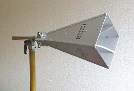
An Antenna with an aperture at the end can be termed as an Aperture antenna. The edge of a transmission line when terminated with an opening, radiates energy. This opening which is an aperture, makes it as an aperture antenna.
Horn antenna is an example of aperture antenna. It is used in satellites in order to cover more area on earth.
Horn antennas are used in microwave frequency range. The same feed horn can be used for both transmitting and receiving the signals. A device named duplexer, which separates these two signals.
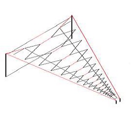
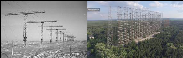
Array Antennas
An antenna when individually can radiate an amount of energy, in a particular direction, resulting in better transmission, how it would be if few more elements are added it, to produce more efficient output. It is exactly this idea, which lead to the invention of Array Antennas or Antenna arrays. Array antennas are used in satellites to form multiple beams from single aperture.
Reflector Antennas
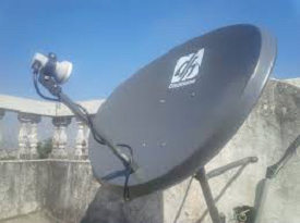
Reflector antennas are suitable for producing beams, which have more signal strength in one particular direction. That means, these are highly directional antennas. So, Parabolic reflectors increase the gain of antennas in satellite communication system. Hence, these are used in telecommunications and broadcasting.
If a Parabolic Reflector antenna is used for transmitting a signal, the signal from the feed, comes out of a dipole or a horn antenna, to focus the wave on to the parabola. It means that, the waves come out of the focal point and strikes the Paraboloidal reflector. This wave now gets reflected as collimated wave front.
If the same antenna is used as a receiver, the electromagnetic wave when hits the shape of the parabola, the wave gets reflected onto the feed point. The dipole or the horn antenna, which acts as the receiver antenna at its feed, receives this signal, to convert it into electric signal and forwards it to the receiver circuitry.
Satellite Communication - Transponders
The subsystem, which provides the connecting link between transmitting and receiving antennas of a satellite is known as Transponder. It is one of the most important subsystem of space segment subsystems.
Transponder performs the functions of both transmitter and receiver (Responder) in a satellite. Hence, the word Transponder is obtained by the combining few letters of two words, Transmitter (Trans) and Responder (ponder).
Block diagram of Transponder
Transponder performs mainly two functions. Those are amplifying the received input signal and translates the frequency of it. In general, different frequency values are chosen for both uplink and down link in order to avoid the interference between the transmitted and received signals.
The block diagram of transponder is shown in below figure.
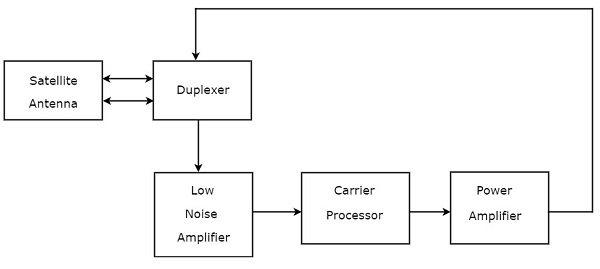
We can easily understand the operation of Transponder from the block diagram itself. The function of each block is mentioned below.
Duplexer is a two-way microwave gate. It receives uplink signal from the satellite antenna and transmits downlink signal to the satellite antenna.
Low Noise Amplifier (LNA) amplifies the weak received signal.
Carrier Processor performs the frequency down conversion of received signal (uplink). This block determines the type of transponder.
Power Amplifier amplifies the power of frequency down converted signal (down link) to the required level.
Types of Transponders
Basically, there are two types of transponders. Those are Bent pipe transponders and Regenerative transponders.
Bent Pipe Transponders
Bent pipe transponder receives microwave frequency signal. It converts the frequency of input signal to RF frequency and then amplifies it.
Bent pipe transponder is also called as repeater and conventional transponder. It is suitable for both analog and digital signals.
Regenerative Transponders
Regenerative transponder performs the functions of Bent pipe transponder. i.e., frequency translation and amplification. In addition to these two functions, Regenerative transponder also performs the demodulation of RF carrier to baseband, regeneration of signals and modulation.
Regenerative transponder is also called as Processing transponder. It is suitable only for digital signals. The main advantages of Regenerative transponders are improvement in Signal to Noise Ratio (SNR) and have more flexibility in implementation.
Earth Segment Subsystems
The earth segment of satellite communication system mainly consists of two earth stations. Those are transmitting earth station and receiving earth station.
The transmitting earth station transmits the information signals to satellite. Whereas, the receiving earth station receives the information signals from satellite. Sometimes, the same earth station can be used for both transmitting and receiving purposes.
In general, earth stations receive the baseband signals in one of the following forms. Voice signals and video signals either in analog form or digital form.
Initially, the analog modulation technique, named FM modulation is used for transmitting both voice and video signals, which are in analog form. Later, digital modulation techniques, namely Frequency Shift Keying (FSK) and Phase Shift Keying (PSK) are used for transmitting those signals. Because, both voice and video signals are used to represent in digital by converting them from analog.
Block Diagram of Earth Station
Designing of an Earth station depends not only on the location of earth station but also on some other factors. The location of earth stations could be on land, on ships in sea and on aircraft. The depending factors are type of service providing, frequency bands utilization, transmitter, receiver and antenna characteristics.
The block diagram of digital earth station is shown in below figure.
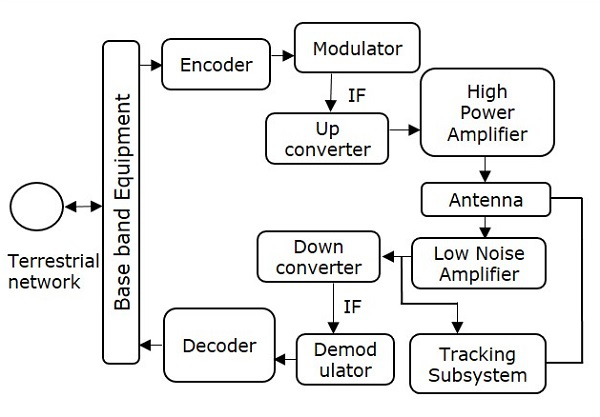
We can easily understand the working of earth station from above figure. There are four major subsystems that are present in any earth station. Those are transmitter, receiver, antenna and tracking subsystem.
Transmitter
The binary (digital) information enters at base band equipment of earth station from terrestrial network. Encoder includes error correction bits in order to minimize the bit error rate.
In satellite communication, the Intermediate Frequency (IF) can be chosen as 70 MHz by using a transponder having bandwidth of 36 MHz. Similarly, the IF can also be chosen as 140 MHz by using a transponder having bandwidth of either 54 MHz or 72 MHz.
Up converter performs the frequency conversion of modulated signal to higher frequency. This signal will be amplified by using High power amplifier. The earth station antenna transmits this signal.
Receiver
During reception, the earth station antenna receives downlink signal. This is a low-level modulated RF signal. In general, the received signal will be having less signal strength. So, in order to amplify this signal, Low Noise Amplifier (LNA) is used. Due to this, there is an improvement in Signal to Noise Ratio (SNR) value.
RF signal can be down converted to the Intermediate Frequency (IF) value, which is either 70 or 140 MHz. Because, it is easy to demodulate at these intermediate frequencies.
The function of the decoder is just opposite to that of encoder. So, the decoder produces an error free binary information by removing error correction bits and correcting the bit positions if any.
This binary information is given to base band equipment for further processing and then delivers to terrestrial network.
Earth Station Antenna
The major parts of Earth station Antenna are feed system and Antenna reflector. These two parts combined together radiates or receives electromagnetic waves. Since the feed system obeys reciprocity theorem, the earth station antennas are suitable for both transmitting and receiving electromagnetic waves.
Parabolic reflectors are used as the main antenna in earth stations. The gain of these reflectors is high. They have the ability of focusing a parallel beam into a point at the focus, where the feed system is located.
Tracking Subsystem
The Tracking subsystem keeps track with the satellite and make sure that the beam comes towards it in order to establish the communication. The Tracking system present in the earth station performs mainly two functions. Those are satellite acquisition and tracking of satellite. This tracking can be done in one of the following ways. Those are automatic tracking, manual tracking & program tracking.
Examples of Earth Stations
In this chapter, let us discuss about two examples of earth stations: Receive-only Home TV system and Community Antenna TV system.
Receive Only Home TV System
If broadcasting takes place directly to home TV receivers, then that type of service is called as Direct Broadcast Satellite (DBS) service.
A mesh type reflector can be used for focusing the signals into a dual feed-horn. It is having two separate outputs. From one output will get C-band signals and from other output will get Ku-band signals.
Television programming mostly originates as first generation signals. These signals are transmitted through satellite to network main end stations in C band. These signals are compressed and transmitted in digital form to cable and DBS providers.
C-band users can subscribe to pay TV channels. These subscription services are cheaper when compared to cable because of the availability of multiple-source programming.
The block diagram of DBS TV receiver is shown in below figure.
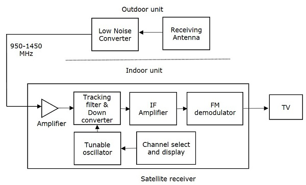
Outdoor Unit
Outdoor unit mainly consists of receiving antenna and Low Noise Converter (LNC). Low Noise Converter (LNC) is nothing but the combination of Low Noise Amplifier (LNA) followed by a converter. The receiving antenna is directly fed into LNC.
In general, the parabolic reflector is also used with the receiving horn antenna for more focusing of the beam.
Indoor Unit
In general, the signal fed to the indoor unit is a wideband signal. The frequency of this signal lies between 950 MHz and 1450 MHz. In indoor unit, this signal gets amplified by using an amplifier.
The amplified signal is applied to a tracking filter and down converter. It selects the desired channel and converts its frequency to an Intermediate Frequency (IF) of 70 MHz.
IF amplifier amplifies the signal strength in order to demodulate it properly. The baseband (demodulated) signal is used to generate a Vestigial Single Side Band (VSSB) signal. This signal is fed into one of VHF/UHF channels of a standard TV set.
Frequency Modulation (FM) is used in DBS TV. Whereas, Amplitude Modulation (AM) in the form of VSSB is used in conventional TV. This is the major difference between DBS TV and conventional TV.
Community Antenna TV System
The Community Antenna TV (CATV) system uses a single outdoor unit and multiple feeds. These feeds are available separately for each sense of polarization. Due to this, all channels will be available at the indoor receiver, simultaneously.
The block diagram of indoor unit of CATV system is shown in below figure.
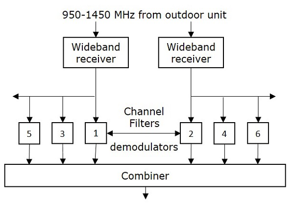
In this case, there is no need of separate receiver to each user. Because, all the carriers are demodulated in a common receiver-filter system. After that, the channels are combined into a multiplexed signal. This signal is then transmitted through a cable to the subscribers (users).
Satellite Communication - Link Budget
In satellite communication systems, there are two types of power calculations. Those are transmitting power and receiving power calculations. In general, these calculations are called as Link budget calculations. The unit of power is decibel.
First, let us discuss the basic terminology used in Link Budget and then we will move onto explain Link Budget calculations.
Basic Terminology
An isotropic radiator (antenna) radiates equally in all directions. But, it doesnt exist practically. It is just a theoretical antenna. We can compare the performance of all real (practical) antennas with respect to this antenna.
Power flux density
Assume an isotropic radiator is situated at the center of the sphere having radius, r. We know that power flux density is the ratio of power flow and unit area.
Power flux density,$\Psi_i$ of an isotropic radiator is
$$\Psi_i = \frac{p_s}{4\pi r^2}$$
Where, $P_s$ is the power flow. In general, the power flux density of a practical antenna varies with direction. But, its maximum value will be in one particular direction only.
Antenna Gain
The gain of practical antenna is defined as the ratio of maximum power flux density of practical antenna and power flux density of isotropic antenna.
Therefore, the Gain of Antenna or Antenna gain, G is
$$G = \frac{\Psi_m}{\Psi_i}$$
Where, $\Psi_m$ is the maximum power flux density of practical antenna. And, $\Psi_i$ is the power flux density of isotropic radiator (antenna).
Equivalent Isotropic Radiated Power
Equivalent isotropic radiated power (EIRP) is the main parameter that is used in measurement of link budget. Mathematically, it can be written as
$$EIRP = G\:\:P_s$$
We can represent EIRP in decibels as
$$\left [ EIRP \right ] = \left [ G \right ] + \left [ P_s \right ]dBW$$
Where, G is the Gain of Transmitting antenna and $P_s$ is the power of transmitter.
Transmission Losses
The difference between the power sent at one end and received at the receiving station is known as Transmission losses. The losses can be categorized into 2 types.
- Constant losses
- Variable losses
The losses which are constant such as feeder losses are known as constant losses. No matter what precautions we might have taken, still these losses are bound to occur.
Another type of loses are variable loss. The sky and weather condition is an example of this type of loss. Means if the sky is not clear signal will not reach effectively to the satellite or vice versa.
Therefore, our procedure includes the calculation of losses due to clear weather or clear sky condition as 1st because these losses are constant. They will not change with time. Then in 2nd step, we can calculate the losses due to foul weather condition.
Link budget calculations
There are two types of link budget calculations since there are two links namely, uplink and downlink.
Earth Station Uplink
It is the process in which earth is transmitting the signal to the satellite and satellite is receiving it. Its mathematical equation can be written as
$$\left(\frac{C}{N_0}\right)_U = [EIRP]_U+\left(\frac{G}{T}\right)_U - [LOSSES]_U -K$$
Where,
- $\left [\frac{C}{N_0}\right ]$ is the carrier to noise density ratio
- $\left [\frac{G}{T}\right ]$ is the satellite receiver G/T ratio and units are dB/K
Here, Losses represent the satellite receiver feeder losses. The losses which depend upon the frequency are all taken into the consideration.
The EIRP value should be as low as possible for effective UPLINK. And this is possible when we get a clear sky condition.
Here we have used the (subscript) notation U, which represents the uplink phenomena.
Satellite Downlink
In this process, satellite sends the signal and the earth station receives it. The equation is same as the satellite uplink with a difference that we use the abbreviation D everywhere instead of U to denote the downlink phenomena.
Its mathematical equation can be written as;
$$\left [\frac{C}{N_0}\right ]_D = \left [ EIRP \right ]_D + \left [ \frac{G}{T} \right ]_D - \left [ LOSSES \right ]_D - K$$
Where,
- $\left [\frac{C}{N_0}\right ]$ is the carrier to noise density ratio
- $\left [\frac{G}{T}\right ]$ is the earth station receiver G/T ratio and units are dB/K
Here, all the losses that are present around earth stations.
In the above equation we have not included the signal bandwidth B. However, if we include that the equation will be modified as follows.
$$\left [\frac{C}{N_0}\right ]_D = \left [ EIRP \right ]_D + \left [ \frac{G}{T} \right ]_D - \left [ LOSSES \right ]_D -K-B$$
Link Budget
If we are taking ground satellite in to consideration, then the free space spreading loss (FSP) should also be taken into consideration.
If antenna is not aligned properly then losses can occur. so we take AML (Antenna misalignment losses) into account. Similarly, when signal comes from the satellite towards earth it collides with earth surface and some of them get absorbed. These are taken care by atmospheric absorption loss given by AA and measured in db.
Now, we can write the loss equation for free sky as
$$Losses = FSL + RFL+ AML+ AA + PL$$
Where,
RFL stands for received feeder loss and units are db.
PL stands for polarization mismatch loss.
Now the decibel equation for received power can be written as
$$P_R = EIRP + G_R + Losses$$
Where,
- $P_R$ stands for the received power, which is measured in dBW.
- $G_r$ is the receiver antenna gain.
The designing of down link is more critical than the designing of uplink. Because of limitations in power required for transmitting and gain of the antenna.
Multiple Access Techniques
Sometimes a satellites service is present at a particular location on the earth station and sometimes it is not present. That means, a satellite may have different service stations of its own located at different places on the earth. They send carrier signal for the satellite.
In this situation, we do multiple access to enable satellite to take or give signals from different stations at time without any interference between them. Following are the three types of multiple access techniques.
- FDMA (Frequency Division Multiple Access)
- TDMA (Time Division Multiple Access)
- CDMA (Code Division Multiple Access)
Now, let us discuss each technique one by one.
FDMA
In this type of multiple access, we assign each signal a different type of frequency band (range). So, any two signals should not have same type of frequency range. Hence, there wont be any interference between them, even if we send those signals in one channel.
One perfect example of this type of access is our radio channels. We can see that each station has been given a different frequency band in order to operate.
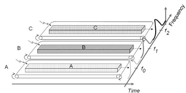
Lets take three stations A, B and C. We want to access them through FDMA technique. So we assigned them different frequency bands.
As shown in the figure, satellite station A has been kept under the frequency range of 0 to 20 HZ. Similarly, stations B and C have been assigned the frequency range of 30-60 Hz and 70-90 Hz respectively. There is no interference between them.
The main disadvantage of this type of system is that it is very burst. This type of multiple access is not recommended for the channels, which are of dynamic and uneven. Because, it will make their data as inflexible and inefficient.
TDMA
As the name suggests, TDMA is a time based access. Here, we give certain time frame to each channel. Within that time frame, the channel can access the entire spectrum bandwidth
Each station got a fixed length or slot. The slots, which are unused will remain in idle stage.
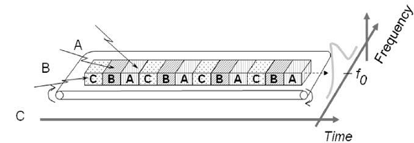
Suppose, we want to send five packets of data to a particular channel in TDMA technique. So, we should assign them certain time slots or time frame within which it can access the entire bandwidth.
In above figure, packets 1, 3 and 4 are active, which transmits data. Whereas, packets 2 and 5 are idle because of their non-participation. This format gets repeated every time we assign bandwidth to that particular channel.
Although, we have assigned certain time slots to a particular channel but it can also be changed depending upon the load bearing capacity. That means, if a channel is transmitting heavier loads, then it can be assigned a bigger time slot than the channel which is transmitting lighter loads. This is the biggest advantage of TDMA over FDMA. Another advantage of TDMA is that the power consumption will be very low.
Note − In some applications, we use the combination of both TDMA and FDMA techniques. In this case, each channel will be operated in a particular frequency band for a particular time frame. In this case, the frequency selection is more robust and it has greater capacity over time compression.
CDMA
In CDMA technique, a unique code has been assigned to each channel to distinguish from each other. A perfect example of this type of multiple access is our cellular system. We can see that no two persons mobile number match with each other although they are same X or Y mobile service providing companys customers using the same bandwidth.
In CDMA process, we do the decoding of inner product of the encoded signal and chipping sequence. Therefore, mathematically it can be written as
$$Encoded\:signal = Orginal\:data\:\: \times\:\: chipping\:sequence$$
The basic advantage of this type of multiple access is that it allows all users to coexist and use the entire bandwidth at the same time. Since each user has different code, there wont be any interference.
In this technique, a number of stations can have number of channels unlike FDMA and TDMA. The best part of this technique is that each station can use the entire spectrum at all time.
Satellite Communication - Services
The services of satellite communication can be classified into the following two categories.
- One-way satellite communication link service
- Two-way satellite communication link service
Now, let us discuss about each service one by one
One-way Satellite Communication Link Service
In one-way satellite communication link service, the information can be transferred from one earth station to one or more earth stations through a satellite. That means, it provides both point to point connectivity and point to multi point connectivity.
Below figure shows an example of one-way satellite communication link service.
Here, the communication takes place between first earth station (transmitter) and second earth station (receiver) on earths surface through a satellite in one direction.
Following are some of the one-way satellite communication link services.
Broadcasting satellite services like Radio, TV and Internet services.
Space operations services like Telemetry, Tracking and Commanding services.
Radio determination satellite service like Position location service.
Two-way Satellite Communication Link Service
In two-way satellite communication link, the information can be exchanged between any two earth stations through a satellite. That means, it provides only point to point connectivity.
The following figure shows an example of two-way satellite communication link service.
Here, the communication takes place between first earth station (transmitter) and second earth station (receiver) on earths surface through a satellite in two (both) directions.
Following are some of the two-way satellite communication link services.
Fixed satellite services like Telephone, Fax and Data of high bit rate services.
Mobile satellite services like Land mobile, Maritime and Aero mobile communication services.
Global Positioning System
Global Positioning System (GPS) is a navigation system based on satellite. It has created the revolution in navigation and position location. It is mainly used in positioning, navigation, monitoring and surveying applications.
The major advantages of satellite navigation are real time positioning and timing synchronization. Thats why satellite navigation systems have become an integral part in most of the applications, where mobility is the key parameter.
A complete operational GPS space segment contains twenty-four satellites in MEO. These satellites are made into six groups so that each group contains four satellites. The group of four satellites is called as one constellation. Any two adjacent constellations are separated by 60 degrees in longitude.
The orbital period of each satellite is approximately equal to twelve hours. Hence, all satellites revolve around the earth two times on every day. At any time, the GPS receivers will get the signals from at least four satellites.
GPS Codes and Services
Each GPS satellite transmits two signals, L1 and L2 are of different frequencies. Trilateration is a simple method for finding the position (Latitude, Longitude, Elevation) of GPS receiver. By using this method, the position of an unknown point can be measured from three known points
GPS Codes
Following are the two types of GPS codes.
- Coarse Acquisition code or C/A code
- Precise code or P code
The signal, L1 is modulated with 1.023 Mbps pseudo random bit sequence. This code is called as Coarse Acquisition code or C/A code and it is used by the public.
The signal, L2 is modulated with 10.23 Mbps pseudo random bit sequence. This code is called as Precise code or P code and it is used in military positioning systems. Generally, this P code is transmitted in an encrypted format and it is called as Y code
The P code gives better measurement accuracy when compared to C/A code, since the bit rate of P code is greater than the bit rate of C/A code.
GPS Services
Following are the two types of services provided by GPS.
- Precise Positioning Service (PPS)
- Standard Positioning Service (SPS)
PPS receivers keep tracking of both C/A code and P code on two signals, L1 and L2. The Y code is decrypted at the receiver in order to obtain P code.
SPS receivers keep tracking of only C/A code on signal, L1.
GPS Receiver
There exists only one-way transmission from satellite to users in GPS system. Hence, the individual user does not need the transmitter, but only a GPS receiver. It is mainly used to find the accurate location of an object. It performs this task by using the signals received from satellites.
The block diagram of GPS receiver is shown in below figure.
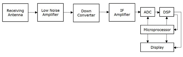
The function of each block present in GPS receiver is mentioned below.
Receiving Antenna receives the satellite signals. It is mainly, a circularly polarized antenna.
Low Noise Amplifier (LNA) amplifies the weak received signal
Down converter converts the frequency of received signal to an Intermediate Frequency (IF) signal.
IF Amplifier amplifies the Intermediate Frequency (IF) signal.
ADC performs the conversion of analog signal, which is obtained from IF amplifier to digital. Assume, the sampling & quantization blocks are also present in ADC (Analog to Digital Converter).
DSP (Digital Signal Processor) generates the C/A code.
Microprocessor performs the calculation of position and provides the timing signals in order to control the operation of other digital blocks. It sends the useful information to Display unit in order to display it on the screen.