- Satellite Communication - Home
- Introduction
- Orbital Mechanics
- Kepler’s Laws
- Earth Orbit Satellites
- Look Angles & Orbital Perturbations
- Launching
- Subsystems
- AOC Subsystem
- TTCM Subsystem
- Power & Antenna Subsystems
- Transponders
- Earth Segment Subsystems
- Examples of Earth Stations
- Link Budget
- Multiple Access Techniques
- Satellite Services
- Global Positioning System
Look Angles & Orbital Perturbations
Earth station will receive the maximum signal level, if it is located directly under the satellite. Otherwise, it wont receive maximum signal level and that signal level decreases as the difference between the latitude and longitude of earth station increases.
So, based on the requirement we can place the satellite in a particular orbit. Now, let us discuss about the look angles.
Look Angles
The following two angles of earth station antenna combined together are called as look angles.
- Azimuth Angle
- Elevation Angle
Generally, the values of these angles change for non-geostationary orbits. Whereas, the values of these angles dont change for geostationary orbits. Because, the satellites present in geostationary orbits appear stationary with respect to earth.
These two angles are helpful in order to point at the satellite directly from the earth station antenna. So, the maximum gain of the earth station antenna can be directed at satellite.
We can calculate the look angles of geostationary orbit by using longitude & latitude of earth station and position of satellite orbit.
Azimuth Angle
The angle between local horizontal plane and the plane passing through earth station, satellite and center of earth is called as azimuth angle.
The formula for Azimuth angle ($\alpha$) is
$$\alpha\: = 180^0 + Tan^{-1}\left(\frac{Tan G}{TanL}\right)$$
Where,
L is Latitude of earth station antenna.
G is the difference between position of satellite orbit and earth station antenna.
The following figure illustrates the azimuth angle.
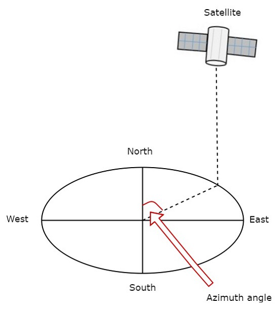
Measure the horizontal angle at earth station antenna to north pole as shown in figure. It represents azimuth angle. It is used to track the satellite horizontally.
Elevation Angle
The angle between vertical plane and line pointing to satellite is known as Elevation angle. Vertical plane is nothing but the plane, which is perpendicular to horizontal plane.
The formula for Elevation angle ($\beta$) is
$$\beta = Tan^{-1}\left(\frac{cosG.cosL-0.15}{\sqrt{1-cos^2G.cos^2L}}\right)$$
We can calculate the elevation angle by using above formula. The following figure illustrates the elevation angle.
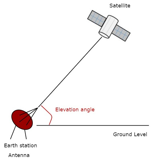
Measure the vertical angle at earth station antenna from ground to satellite as shown in the figure. It represents elevation angle.
Orbital Perturbations
Following are the orbital perturbations due to gravitational and non-gravitational forces or parameters.
Irregular gravitational force around the Earth due to non-uniform mass distribution. Earths magnetic field too causes orbital perturbations.
Main external perturbations come from Sun and Moon. When a satellite is near to these external bodies, it receives a stronger gravitational pull.
Low-orbit satellites get affected due to friction caused by collision with atoms and ions.
Solar radiation pressure affects large GEO satellites, which use large solar arrays.
Self-generated torques and pressures caused by RF radiation from the antenna.
Most satellites use a propulsion subsystem in order to maintain a proper spin axis direction and control the altitude of the satellite against perturbation forces.
