- Solar Energy - Introduction
- Solar Energy - Photovoltaic Effect
- Developing Solar Panel
- Solar Energy - Cell Efficiency
- Types of Photovoltaics
- Geothermal Energy
- Geothermal Energy - Introduction
- Geothermal Energy - Extraction
- Geothermal Energy - Geophysics
- Hydroelectric Power
- Hydroelectric Power - Introduction
- Hydroelectric Power - Turbine Types
- Hydroelectric Power Systems
- Hydraulic Ram Pump
- Renewable Energy Resources
- Renewable Energy - Quick Guide
- Renewable Energy - Resources
- Renewable Energy - Discussion
Renewable Energy - Quick Guide
Renewable Energy - Introduction
Renewable energy is a term used to refer to forms of energy that are naturally obtained from the environment and from sources that can be replenished naturally. These include solar energy, wind energy, geothermal energy, hydropower, and biomass.
The term renewable energy should not be confused with alternative energy, which describes sources of energy outside the regular forms like gasoline that are considered more environment-friendly or less harmful.
Advantages of Renewable Energy
Advantages of using renewable sources of energy are −
Less maintenance cost as most sources entail few or no moving parts, hence, less mechanical damages.
They are economical and can cut costs spent on fossil fuel.
They emit little or no waste in the environment.
Renewable energy sources do not deplete. Therefore, these have a better prospect for the future.
Sources of Solar Energy
This tutorial explains five major sources of renewable energy. Each source will be reviewed briefly, although detailed discussion will be provided in the subsequent chapters.
Solar energy − Energy from the Sun is referred to as solar energy. Solar energy could be used as either active solar or passive solar. Active solar is directly consumed in activities such as drying clothes and warming of air. Technology has provided a number of ways to utilize this abundant resource.
Geothermal energy − This refers to heat energy stored under the ground for millions of years through the earth formation. It utilizes a rich storage of unutilized thermal energy that exists under the earths crust.
Hydro-power − This is a major renewable energy source used all over the world today to produce electricity.
Wind energy − In ancient times, wind energy was used to move ships by impacting on the sails.
Biomass energy − In energy generation, it refers to waste plants that are utilized to generate energy by combustion.
Solar Energy - Introduction
Solar energy is the energy obtained by capturing heat and light from the Sun. Energy from the Sun is referred to as solar energy. Technology has provided a number of ways to utilize this abundant resource. It is considered a green technology because it does not emit greenhouse gases. Solar energy is abundantly available and has been utilized since long both as electricity and as a source of heat.
Solar technology can be broadly classified as −
Active Solar − Active solar techniques include the use of photovoltaic systems, concentrated solar power and solar water heating to harness the energy. Active solar is directly consumed in activities such as drying clothes and warming of air.
Passive Solar − Passive solar techniques include orienting a building to the Sun, selecting materials with favorable thermal mass or light-dispersing properties, and designing spaces that naturally circulate air.
Conversion of Solar Energy
The solar energy is the energy obtained by capturing heat and light from the Sun. The method of obtaining electricity from sunlight is referred to as the Photovoltaic method. This is achieved using a semiconductor material.
The other form of obtaining solar energy is through thermal technologies, which give two forms of energy tapping methods.
The first is solar concentration, which focuses solar energy to drive thermal turbines.
The second method is heating and cooling systems used in solar water heating and air conditioning respectively.
The process of converting solar energy into electricity so as to utilize its energy in day-to-day activities is given below −
Absorption of energy carrying particles in Suns rays called photons.
Photovoltaic conversion, inside the solar cells.
Combination of current from several cells. This step is necessary since a single cell has a voltage of less than 0.5 V.
Conversion of the resultant DC to AC.
In the next chapter, we will learn the Photovoltaic method of converting solar energy into electricity.
Solar Energy - Photovoltaic Effect
It is essential that we have some basic knowledge of PN Junctions before moving on to learn the concept of Photovoltaic Effect.
The PN Junction
The PN Junction was invented by Russell of Bell laboratories in the USA. It refers to a junction between two semiconductors, that is, P-Type and N-type. Russell discovered that the two semiconductors have an interesting behavior at the junction that causes conduction in one direction only.
A P-type semiconductor has holes (absence of electron) as majority charge carriers. An Ntype semiconductor has electrons as majority charge carriers.
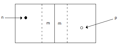
In the diagram given above, at the junction −
Extra charges diffuse across to the opposite junctions such that the positive on the p-side gain negative charges and neutralize them.
Similarly, the negatives at the N-side gain positive charges and neutralize them.
This forms a margin (m) at either side where extra charge are depleted to make this region neutral and at a state of equilibrium. This region is referred to as a depletion layer and no charge from either side crosses.
The depletion layer offers a potential barrier and thus requires external voltage to overcome it. This process is called biasing.
To conduct, in forward biasing, the applied voltage should pump electrons (negative) from n-junction towards the p-side of the junction. Continuous flow of current guarantees a constant movement of electrons to fill holes, hence conduction across the depletion layer.
Reversing the applied voltage, in a process called reverse biasing, causes holes and electrons to drift apart, increasing the depletion layer.
An external load is connected to a solar cell with positive terminal connected to the N- side wafers and the negative terminal to the P- side wafers. A potential difference is created by photovoltaic effect.
The current obtained by electrons displaced by photons is not sufficient to give significant potential difference. The current is therefore contained to cause further collisions and release more electrons.
Photovoltaic Effect
A solar cell utilizes the concept of a p-n junction in capturing the solar energy. The following figure shows the fermi level of a semiconductor.
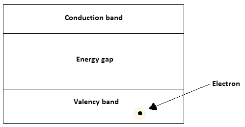
For a semiconductor to conduct, electrons must cross the energy gap from the valence band to the conduction band. These electrons require some energy to dislodge and move across the valence gap. In solar cells, photons emitted from the Sun provide the required energy to overcome the gap.
A photon incident on the surface could be absorbed, reflected, or transmitted. If it is reflected or transmitted, it does not help dislodge an electron and is thus wasted. Therefore, a photon must be absorbed to provide the energy required to dislodge and move electrons across the valence gap.
If Eph is the energy of a photon and EG is the threshold energy to cross the energy gap, then the possible outcomes, when photon hits the surface of a semiconductor are −
Eph < EG − In this case, the photon does not attain the threshold and will just pass through.
Eph = EG − The photon has the exact threshold to dislodge an electron and create a hole electron pair.
Eph > EG − The photon energy surpasses the threshold. This creates an electron-hole pair, though it is a waste, since the electron moves back down the energy gap.
Absorption of solar radiation
In most cases, absorption coefficient of the semiconductor is used to determine the efficiency of absorbing energy from Sun. Low coefficient means poor absorption. Therefore, how far a photon goes is a factor of both absorption coefficient (α) and wavelength of the radiation (λ).
$$\alpha\:=\:\frac{4\pi k}{\lambda}$$
Where, k is the extinction coefficient.
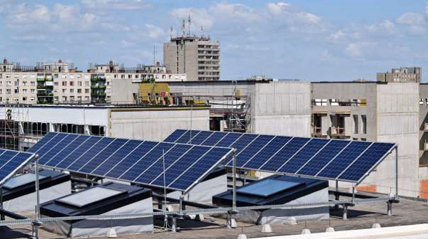
Solar Energy - Developing a Solar Panel
To construct a solar panel, one requires several solar cells made of doped silicon as has been discussed before. These cells are connected in series to add up the resultant current. This gives strips of clustered cells called a module. A single module could be constructed into a solar panel or combined with others in cases where a large panel is required.
A solar panel consists of several layers that sandwich the photovoltaic cells. These layers are used to protect the fragile cells.
An illustration of the layers is given below −
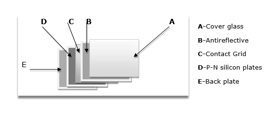
The layers consist of the following parts −
Cover Glass − This is the top cover and is transparent to allows light to enter. It prevents the cells from mechanical damage. It is made of hard glass to prevent against scratch.
Non-reflective layer − Silicon can reflect most of the sunlight. Therefore, this layer is used to counter this and ensure maximum absorption of photons. In other words, it helps to maximize absorption.
Contact grid − At this layer, all the contacts joining top to bottom of cells are connected together. The contact extends to the external parts of the panel like charge controller, combiner box and battery storage or grid system.
P and N Silicon plates − This layer is actually a combination of two layers − the Ndoped silicon layer and P-doped silicon layer. This layer gives the solar panel its color.
Back plate − This is a hard layer for supporting the crystalline photovoltaic panels. At times, flexible synthetic fibers may be used for thin-film type panels.
Aluminum frame is used to frame the panel and to make it weatherproof. The benefits are −
The frame provides a means of mounting the panel on surfaces such as rooftops.
The frame is tight enough to protect the panel against extreme weather conditions such as storms.
The solar panel should also be under constant care to prevent dust particles from resting on it. During the installation process, the panels should be fixed at an angle to receive maximum light. A proportional battery should be set in place in cases of no direct usage, to avoid waste.
Solar Energy - Cell Efficiency
Efficiency refers to the ratio of power input to power output. In the case of a photovoltaic, efficiency is the ratio of power output in terms of electricity to the solar energy incident on the cell.
Now, Output power, pm = Voltage (v) * current (I) in the circuit (max value).
And, Input power Pi = Incident energy G (Wm-2) * Surface area of cell, A (m2).
Thus, Efficiency is calculated as −
$$\eta\:=\:\frac{P_{m}}{G\: \times\:A_{c}}$$
Where, Pm must be the maximum power of the circuit. It is obtained by using the voltage across open circuit (Voc) and current across the short circuit (Isc) and the fill factor (FF).
$$P_{max}\:=\:V_{OC}I_{SC}FF$$
These measurements must be measured under standard conditions i.e. 25C, Air mass of 1.5gm-3, and incident energy, G of 1000Wm-2.
The factors that affect output of a photovoltaic cell include −
- The wavelength of the incident light
- Recombination of electrons and holes
- Electrical resistance
- Temperature
- Fill factor
- Reflection factor of the material
Therefore, to maximize power, the cell should be constructed to have a greater fill i.e. surface area utilized. Positioning of a solar cell also determines its output for two reasons. First, the angle determines the level of reflection on the cell, and secondly the positioning determines the amount of sunshine captured from 9 am to 3 pm. For maximum efficiency, it is important to avoid any shadowing on cells.
Solar Energy - Types of Photovoltaics
The Photovoltaic technology utilizes two technologies; crystalline form and the amorphous silicon. The amorphous is still a new exploration and may take longer to achieve optimal performance.
Crystalline cells
The crystalline silicon technology gives two types of photovoltaic cells −
Mono-crystalline cells − Mono-crystalline solar cell is constructed from a single crystal cylinder sliced off to produce all the wafers in the array. The wafers are circular in shape, though at times they may be cut into other shape variations for crystal utility purposes. It is characterized by a uniform blue color. Other features include −
Relatively high efficiency, among all PV technologies, available today.
Most expensive cells because it is developed from purely same crystal.
The cells are rigid and have to be well positioned and mounted on a rigid backing.
Poly-crystalline cells − These are also known as malty-crystalline cells and are made by casting the silicon into a square mould. The resulting cast is then cut into a number of square wafers. The square block is made up of several crystals composed of arrays of blue variations. This is the technology behind the glittery, gemstone-like surface of some solar panels in the market today. Poly-crystalline cells have distinct features including −
Slightly less efficient compared to mono-crystalline cells.
Cheaper than mono-crystalline.
Less waste of material (purified silicon).
Given solar panels of same specification, the poly-crystalline panel is slightly wider than the mono-crystalline counterpart.
Amorphous Cells
Thin-Film PVs − The use of amorphous form of silicon to make photovoltaic cells is a new technique that the experts are still researching to curb the challenges of the crystalline forms. The characteristics of this technology include −
They are much cheaper than both the crystalline forms.
They are flexible. Thus, they should have a movable mounting to best utilize this feature. However, the shape of the surface should accommodate the panel for safety purposes.
Less susceptible to power loss due to shedding of cells. In addition, they are more powerful at a dimly lit environment.
Less durable. They gradually degenerate in terms of power production especially for the first month before gaining stability.
Least efficient in power production and therefore covers larger space
The new technology makes it possible for the panel to be mounted on windowpanes and curved surfaces.
Photovoltaic Circuit Properties
An equivalent circuit of a photovoltaic cell is given below −
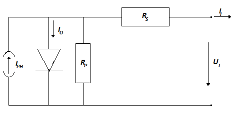
Current obtained, Iph = Area of cell * Intensity of light, H * response factor, ξ.
Given, Loss due to resistance by conductor = Rp
Loss due to non-ideal conductors = Rs
If the cell produces current I at a voltage V, then, The relationship between I and U of a single cell is expressed as −
Current, $I\:=\:I_{ph}-I_{o}[\exp\lgroup\frac{\lgroup U_{cell}+I_{cell}R_{s}\rgroup}{U_{t}}-1\rgroup]-\frac{\lgroup U_{cell}+I_{cell}R_{s} \rgroup}{R_{p}}$
Where thermal voltage is given by $U_{t}\:=\:\frac{qkT}{e}$
Temperature is in Kelvin and K = 1.38-23(Bowmans const), e = 1.602e-19.
Getting maximum I and U, we can obtain maximum power.
Imax is obtained when V = 0 i.e. short circuit while Vmax is obtained when I = 0 i.e. open circuit.
Note − Cells in parallel add current while cells in series add up voltage.
Geothermal Energy - Introduction
Geothermal energy refers to heat energy stored under the ground for millions of years through the earth formation. It utilizes a rich storage of unutilized thermal energy that exists under the earths crust.
Geothermal energy is site specific but can be very cheap especially when used for direct heating. It is a challenge to estimate power from this source since it occurs underground at extremely high temperatures.
The earths crust has immense heat (thermal) energy stored over millions of years. There exists a huge temperature difference between the earths crust and the surface. The temperature difference is known as geothermal gradient. This energy is sufficient to melt rock. The molten rock, called magma, at times erupts through cracks on earth surface as volcanoes. Geothermal energy is converted to produce to electricity.
The presence of geothermal deposits in form of hot geothermal fluid is a sign of a good site. The site should have a shallow aquifer to allow injection of water. The inherent geothermal product should be about 300o F.
Advantages of Geothermal Energy
The major advantages include −
No fuel is burnt since heat is derived from an abundant underground reservoir. The renewable energy source could solve the risk of running out of fossil fuels.
It has no emissions and produces 10% carbon dioxide, which is very little compared to the amount consumed by plants.
Unlike other sources of renewable energy (solar, wind and water), it is not affected by whether and will always be available throughout the year.
Geothermal energy is relatively less expensive especially when directly used, for example, as source of heat in greenhouses.
The only disadvantage of geothermal energy is the release of hydrogen sulfide identified by the signature rotten egg smell.
Enhanced Geothermal Sources (EGS)
In some geothermal sources, water is injected into the wells containing geothermal deposits. Inside these deposits, water gets superheated and hence changes into steam. Water is pumped down under very high pressure to expend rock fissures.
Some lower temperature geothermal energy is utilized directly as heat. Green houses may be supplied with this energy as temperature regulator. This technique is also used in fisheries and mineral recovery.
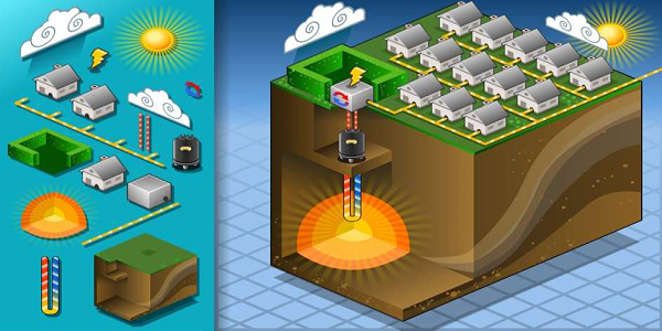
Geothermal Energy - Energy Extraction
The principle is to use heat energy through heating of water to steam. Geothermal energy utilizes high temperatures below the earths crust. The hot steam or water heats a fluid that in turn expands to turn turbines that generate electricity.
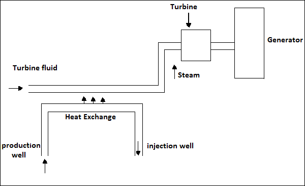
There are three forms that are utilized. They are as follows −
Dry-steam power stations
Basically, dry steam stations utilize the steam that flows out of geo-deposits to heat a secondary fluid that turns turbines to generate electricity. The steam emerges at a temperature of up to 150 degrees, hot enough to expand the fluid in the geothermal plant. This is one of the oldest techniques of geothermal electricity. The expansion of the secondary fluid produces mechanical energy needed for turning the turbines to generate electricity.
Flash steam power stations
Water in wells under high pressure is drawn to a region of lower pressure. This pressure shift vaporizes the water emitting steam at high temperature. This steam is separated from the water and used to heat up the fluid that turns the turbines in the generator. At this pressure, the gas is at a very high temperature.
Binary cycle power stations
Exploiting the difference in boiling points, as determined by density, is the most recent method used. A fluid with a much lower boiling point than water is used in the system. This method uses water at temperatures 58 degrees to heat a secondary fluid of a lower boiling point. Water heats up the fluid and causes it to vaporize, due to lower boiling point, and turns the turbines to generate electricity.
Geothermal Energy - Geophysics
Geophysics is a field of science that deals with the properties of the earth and its environments. It is the study of magnetic and gravitational fields, internal properties of the earth, water cycles, mineral deposit formation, and the solar terrestrial relations.
Geophysics specializes in finding resources under the earths crust and determining the potential threats such as earthquakes. It also entails qualitative analysis to identify the best sites for mining, oil drilling and geothermal deposits.
Branches of Geophysics
Various branches of Geophysics are −
Study of solid earth − Solid earth properties range from tectonic study to seismic analysis for earthquakes. This branch studies the oil and mineral deposits. The soils samples are analyzed for any unusual deposits or textures.
Study of water − This is the study of fresh water as well as water under the earth surface. Study of water is done by hydrologists who analyze water cycles and water tables. Oceanography, the study of the oceans and the ground beneath, also falls under this category.
Study of air − Air is a major component of the earth. The study of air helps in predicting weather conditions and guard against extreme conditions such as hurricanes.
Life and geophysics − The interaction of organisms and the earth is an important factor. It is important to note that oil deposits mainly result from decaying matter. Conditions below the ground are studied to assess their effect on the existence of organisms.
Aquifers
Some rocks, called aquifers, provide a good environment for water to flow through naturally. These rocks are porous and filter water running through. Aquifers are best sites where wells are drilled to provide constant water flow. Rocks that make good aquifers are sand, granite, conglomerate, sandstone, and fractured lime.
Aquifers lie underneath the water table such that precipitation immediately replenishes water pumped from wells. Aquifers are very important in sustaining the earths water cycle. Wells are drilled into aquifers surrounded by non-porous rock. These rocks generate pressure that helps in pumping the water. These kinds of wells are known as artesian wells.
Hydrogeology Tests
Hydrogeology utilizes several tests in aquifers to capture their characteristics. These tests are conducted in controlled environments called control wells.
The three major tests are −
Pumping test − Water is extracted and pumped back into the well at constant intervals. Behavior of neighboring wells is recorded as a result of the changes. This test helps in determining the permeability of the aquifers surrounding the well.
Slug test − Slug means a swift change in water level. In this test, the effect on the neighboring wells and the duration it takes to recover its original level is measured. This could be achieved by drawing from the lake or water could be pumped into the well to drastically change the level.
Constant-head test − This is done using an experimental well called a control well. In a control well the thermal drawdown can be maintained at a level. The effect is recorded for the neighboring wells. Drawing from the well regularly may dent the water table. This may cause depression and cause abnormal flow.
Hydroelectric Power - Introduction
Hydro Electric power (HEP) is a major renewable energy source used all over the world today to produce electricity. It utilizes the basic laws of Physics. Falling water under high pressure has high kinetic energy. In an HEP station, the falling water turns the turbines. Through magnetic induction, the generator converts the mechanical energy of the turbines to electricity.
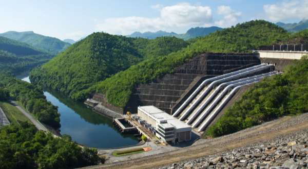
Hydroelectric Power Station
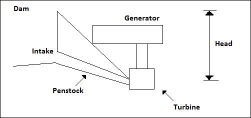
It is the technique of using dam water falling from a height to turn the turbines of a generator. The mechanical energy is converted into electrical form and fed into the national grid system. The following diagram shows an outline of a hydroelectric power station.
The location of a hydroelectric power station must be analyzed by an expert to determine the effective head for maximum efficiency. Hydraulic systems are also used to utilize the concept on slower and slow moving water streams.
One advantage of hydropower is that the water is available for other use after generation. A river with high water flow and head is a better source of hydropower.
Flow rate means the speed at which water passes a particular point in the river per second. The head refers to the vertical distance from the top of the slope to the power station.
A dam with a large drop is constructed to raise the potential energy of water. The intake is placed at the bottom where the pressure is highest. Water then flows by gravity through the penstock. At this level, kinetic energy is sufficient to turn the turbines.
Power Estimation
The power in a dam can be estimated by two factors - flow of the water and the head.
Flow means the volume passing through a given section of a river at a given time. Flow is given by m3/s.
Head is the vertical distance the water falls through.
Theoretically, Power is directly proportional to the above mentioned factors, i.e.
P = Q*H*c
Where,
P − power expected
Q − the flow in m3/s
H − Head in m
c − constant (density* gravity)
Therefore, taking density of water as 1000gm-3 and gravity 1.9 −
P = 1000*1.9*Q*H
Energy is required to turn the turbines of a generator to cause an electromagnetic induction.
Pumped storage is a technique used to recycle water after it has passed through the turbines. In particular, pumped storage improves the overall dams efficiency.
A hydroelectric power station has three major components. They are −
The first is the dam that creates the water head. Water falls from the base of the dam at high velocity and provides kinetic energy to turn the turbines.
The second component is the reservoir. The water reservoir is the place behind the dam where water is stored. The water in the reservoir is located higher than the rest of the dam structure. The height of water in the reservoir decides how much potential energy the water possesses. The higher the height of water, the more its potential energy.
The third component is the electric plant where electricity is produced and connected to the grid.
Resource Assessment for Small Installation
Before installing a mini-hydro plant, it is important to identify nearby resource that can be harnessed. A good stream with a fairly constant flow (m3/s) is a resource worth exploiting.
A river with good flow can utilize the velocity of the water to turn the water wheel. Mountain or hill slopes are best suited for hydro-generation. As mentioned before, it is necessary to consider both head and flow of the river to determine the approximate power output.
Knowing the parameters, approximate power is determined as follows −
Head in feet * flow in gallons per meter / 10 = power in Watts
The head could also have the units of Pressure for an even river.
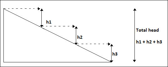
Hose Tube Method
This technique is used in determining the head in a low stream for a submersed turbine.
The requirements for a hose tube method include a flexible piping (preferred garden horse), a funnel, and a measuring material. The stream should be shallow enough for one to wade through (check river depth before beginning). The procedure for installing a hose tube method is described below.
First, stretch the hose from the point where the stream starts to slope. Second, lift the end of the hose till water stops flowing through. Take the vertical distance and repeat the same for other sections till the preferred site is reached. The figure below illustrates the various heads in each section.
Determining head
Determining Flow
The flow of a normal stream for a domestic hydropower could be determined by the following two methods −
Float method − in this technique, a float of measured weight is released in an even part of the stream and time taken to cover measured distance is recorded. The distance in meters is divided by the time taken in seconds to get the velocity. It is worth to note that the float should not touch the ground. In case it is too heavy such that it touches the stream bed, a smaller float may be chosen.
Bucket method − This is achieved by damming the stream and diverting it into a bucket. The rate it takes for it to fill is then recorded. This is done in gallons per second. Use a bucket with a standard measure to be more accurate.
Hydroelectric Power - Turbine Types
There are two broad classifications of turbines namely Impulse turbines and Reaction turbines. The choice of turbines relies on the head and flow. Other factors to consider are depth, cost, and the efficiency required.
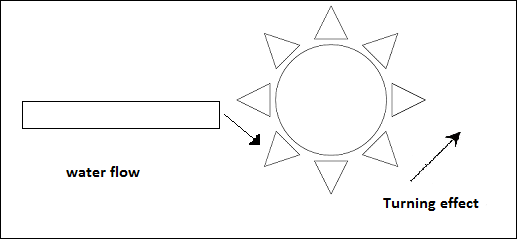
Impulse Turbines
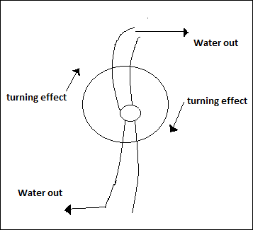
In impulse turbines, the velocity of water hits the buckets of the turbine wheel to create mechanical energy. Water runs off the bottom of the turbine after turning the wheel.
In impulse turbines, the velocity of water hits the buckets in the turbine wheel to create mechanical energy. Water runs off the bottom of the turbine after turning the wheel.
Types of Impulse Turbines
Impulse turbines are of two types −
Pelton wheel − This type of wheel has jets that direct water into an aerated space. Water falls on the buckets of the runner and causes a turning moment. This wheel requires no draft tubes. A variation was developed called the turgo-wheel that looks like fan blades enclosed in the edges. Water simply runs through the fans and causes rotation. It is designed for high head and a low flow.
Cross-flow − the wheel has drum-like section with elongated nozzle and rectangular in shape. The opening guide vanes direct water to the runner. Water flows through the blades twice as it goes in and flows out.
Reaction Turbines
In Reaction turbines, power is developed from both pressure and the impact of moving water because the runner is located at the center of the stream. These are mostly suited for higher flow and lower head. Water hits all the blades rather than individual blade at a time.
Reaction turbines are of three types −
Propeller turbines have a runner with three to six blades. Water hits all the blades constantly at constant pressure to balance the runner. There are variations of propeller turbine, that is, bulb, Kaplan, tube and straflo.
Francis turbine uses a runner with nine or more fixed buckets. Water is allowed to flow just above the turbine to create a constant spinning motion.
Free-fall turbines utilize the kinetic energy in water and not the potential energy used by most turbines. That is why these are commonly known as kinetic turbines. They operate under natural setting of streams and rivers. They may also operate with ocean tides.
Hydroelectric Power - Hydroelectric Systems
Hydropower could be utilized for domestic consumption when there is a constant water flow. In most cases, the flow and fall do not provide enough power to turn conventional turbines. To solve this problem, small systems referred to as micro-hydro systems are available in the market today. The systems are made up of small generators installed in the rivers or creeks and run on impulse turbines. In fact, most use the Pelton wheel.
Components of a Hydroelectric Power Plant
The following are the major components of a micro Hydroelectric power plant −
Intake − The position of the generator must be near an intake. This could be achieved by damming the water to establish the necessary head and to build up pressure.
Penstock − It is a region of gravitational fall from the intake. For micro-hydro projects, pipes are used from intake to the runner of the turbine.
Turbines − The type of turbine to use relies on the size of the stream and the desired output. For most small hydros, a pelton wheel is efficient. In cases of low head, submersible reaction turbines may be used in which case the water pressure turns the blades.
Controls − Controls prevent overcharging of the battery. They regulate this by diverging excess power to the dump load.
Dump load − This is simply an alternative high resistance destinations used when the battery is fully recharged. They may include water heaters or even air conditioning system.
Battery − Micro-hydro systems do not produce large power like conventional AC systems. In order to utilize it for a number of power needs, accumulation of energy is necessary. Batteries provide a means to store the power to the amount desired. They also provide energy during outages in the system supply.
Metering − This is important to monitor power usage vis--vis power supply. This may help in understanding important system characteristics as well as identification of faults.
Disconnect − In any electric wiring system, there should be a guard against excess power supply. A circuit-breaker gadget should be installed on the mains to guard against damage on any gadget connected to the hydro supply.
Hydroelectric Power - Hydraulic Ram Pump
A hydraulic ram pump works under basic laws of physics to lift water against gravitational pull to a height higher than that of the source. This pump works without any external energy supply such as burning of fuel. The only energy is the kinetic energy of the water being pumped. The greater the head the higher the distance pumped.
How it Works?
To understand how the ram pump works, it is important to have knowledge of water hammer principle.
Fluid hammer − The fluid hammer effect occurs when a fluid (in this case water) is forcefully stopped or its direction changes suddenly. A pressure shock is experienced and the wave is conducted back to the source of the fluid. This could be a dangerous phenomenon causing tires and pipes to burst or collapse.
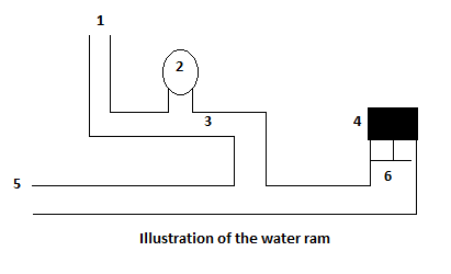
Water flows into the pump through inlet (5) with some kinetic energy from the head and shuts the valve (6).
With 6 closed and 3 initially closed, the water develops a water hummer that builds up pressure in the pipe and opens valve (3) sending some water through the outlet (1).
Since the flow is up hill, water flows slowly and shortly falls back again closing 3.
The water hammer builds up and replicates back through the pipe producing a suction force that opens the waste valve 6.
The process is repeated with pressure building up each time.
Label 2 is a pressure controller containing air. It cushions the shock whenever 6 closer and water is pushed through 3. It helps protect the piping from impact that could lead to bursting as well as aid the pumping effect. The ram is 60 to 80 percent efficient. This does not directly reflect the ratio of water pumped as it relies on the vertical height of water pumped. In other words, this is the efficiency of the pumping effect to energy from the water hummer effect.
Solved Example 1
Calculate the estimated power for a turbine rated with 85 percent efficiency. The flow of the river is 80 cubic meters per second and the streams intake is situated 147 meters from the location of the generator turbines.
Solution −
Power is given by W = Efficiency * head * flow * density * gravity
Converting specific density of water to SI units, we get 1000kgm-3
Substituting the values in the formula −
P = 0.85 * 1000 * 80 * 9.81 * 147
P = 97 Mega Watts
Solved Example 2
Given the actual power received in a particular day was 1,440,000kWh; calculate the efficiency of the generator. Assume gravity to be 9.81 ms-2. Specific density of water 1 gcm-3.
Solution −
Given: 1 days supply = 288000 kWh
Power = 1440000/24
= 60 mW
Efficiency = Power supply/ expected power * 100
= 60/97 * 100
The system is 66.67% efficient.
Wind Energy - Introduction
In ancient times, wind was used to move the sails of the ships. In this chapter, we will see how wind energy is used to generate electricity.
A turbine converts the kinetic energy of the wind to useful mechanical energy. This energy could be used in mechanical form or turn generator turbines and provide electricity. Just like in the hydropower systems, wind energy is harnessed through conversion of the wind kinetic energy to mechanical energy.
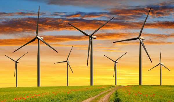
The wind turbines are largely classified into two types- Horizontal Axis Wind Turbines and Vertical Axis Wind Turbines. Large areas installed with wind turbines, that is, wind farms are increasingly emerging today.
Wind Characteristics
There are general characteristics of wind while others are more specific to the site. Some of the site specific characteristics include −
Mean wind speed − This estimates the annual wind yield though it does not give the distributions.
Wind speed distribution − There are three aspects namely annual, diurnal and seasonal characteristics. Understanding the wind speed variations and the spread is necessary when choosing a site.
Turbulance − This is the chaotic movement of wind in unpredictable patterns. Turbulance results from continuously changing properties of wind motion that impact on energy production and fatigue on blades.
Long term fluctuation − Irregular wind causes unpredictable energy supply. Before a wind turbine is set, the area should be studied for a constant wind flux.
Distribution of wind direction − This is more significant in positioning of the blades especially for horizontal axis types.
Wind shear − Shear is change in wind direction, speed or the height at which the maximum velocity occurs.
Wind Speed Patterns
Wind patterns are important and are often analyzed using a wind spectrum. A high value of the wind spectrum represents a large change in the wind speed at the given time interval. If represented on a graph, the peaks depict turbulences that occur with time.
Wind speed distribution
There are three distributions −
Diurnal − Caused by the difference between temperatures during the day and at night.
Depressions − Occur with four-day intervals along the coastal region.
Annual − Distribution is latitude dependent.
Wind Energy - Basic Theory
To understand wind energy, we subscribe to the theory of conservation of mass and conservation of energy. A duct shown below is assumed to represent wind flowing in and out of the blades of the turbine.
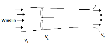
The velocity Va is assumed to be the average of V1 and V2. Kinetic energy at the mouth of the tube is given by −
KE = 1/2 mV2
KE of energy changed = 1/2 mV12 - 1/2 mV22
1/2 m(V12 - V22)
Since m = p.A.Va then KE change, Pk = 1/2 p.A.Va (V12 - V22)
On further simplification, the estimated wind energy is give as −
KE, pk = 0.5925 * 1/2pAV13
Blade Element Theory
The blade element theory assumes that the flow at a given part of a wind turbine blade does not affect the adjacent parts. This subdivision on the blade is called annulus. The momentum is calculated for each annulus. All the resultant values are then summed up to represent the blade and hence the entire propeller.
On each annulus, an equally distributed velocity is assumed to have been induced.
Dynamic Matching
The dynamic inflow model was incorporated to improve the estimations by the Blade Element and Momentum theory. The basic dynamic in flow theory concept helps estimate the effect of blade turbulence. The swept area is given a dynamic state to help in deriving estimate mean velocity.
The BEM theory gives estimates only at steady wind but it is obvious that turbulences must occur. However, this is accounted for by the basic dynamic inflow model to provide a more realistic estimate.
Wind energy produced, especially in the horizontal axis type, is known to be the product of tip speed, the total number of blades used and the lift-to-drag ratio of the side with an aerofoil. The readjustment to a new steady state of equilibrium is well explained by the Dynamic Inflow Method (DIM).
Dynamic Inflow Method
DIM is also known as dynamic wake theory and is based on the induced flow, which is normally not steady. It calculates the inflow vertical to the rotor taking into consideration its effect on the dynamic flow.
This simply takes into consideration the wake effect or simply the velocity of the air vertically aligned with the rotors caused by the turning of the blades. It however assumes the tangential velocity to be steady. This is referred to as the Wake effect and its drag lowers the efficiency of a wind turbine.
Electricity Generation
The kinetic energy in wind is converted to electricity by wind turbines. They use the ancient concept used in windmills though with inherent technology, such as sensors, to detect wind direction. Some wind turbines have braking system to halt in case of strong winds to protect the rotor and blades from damage.
There are gears connected to the rotor shaft to accelerate the blades to a speed suitable for the generator. Inside the generator, electromagnetic induction (the basic method of conversion from mechanical energy to electricity) occurs. The shaft rotates a cylindrical magnet against an electric wire coil.
All electricity from the turbines in a wind power station is assimilated to a grid system and converted to a high voltage. This is actually the conventional technique of transmitting electricity in the grid system.
Large surface-tipped blades are needed although this should be determined by the noise that results from wide blades. A wind farm may have up to 100 generators, which will result in more noise.
Wind Energy - Wind Turbine Types
There are two broad classifications of wind turbines −
- Horizontal Axis Wind Turbines (HAWT)
- Vertical Axis Wind Turbines (VAWT)
Lets discuss these two types of wind turbines in a little detail.
Horizontal Axis Wind Turbines
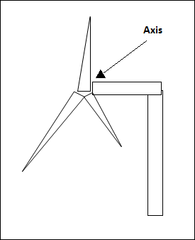
These are windmill-like turbines with the top of the shaft pointing towards the wind direction. Since they have to be pointed towards the wind, smaller turbines are directed by wind vanes mounted on the structure. Larger turbines have wind sensors with servo to turn the turbines.
They are also fitted with gear-boxes to accelerate the slow rotation to make it strong enough for the generator turbines. The blades are stiff enough to avoid breaking or bending due to the turning moment of the wind.
This type is mounted on a tower; hence they experience high velocity winds. They are slightly bent to reduce the sweep area. A lower sweep area reduces resistance, which may cause fatigue and failure.
Vertical Axis Wind Turbines
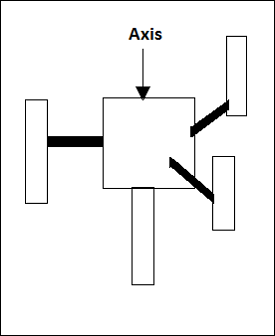
The main root is mounted on the vertical shaft. This eliminates the difficulties associated with horizontal wind turbines. The subtypes include −
Darius Wind Turbine
This is also known as the egg-beater turbine and resembles a huge egg beater. It is efficient but may have more down times and hence less reliable. To improve on solidity (blade area over rotor area) three or more blades should be used.
Savonious Wind Turbine
These types have a greater reliability than Darius turbines. The problem is that they cannot be mounted on top of towers. Therefore, they are exposed to turbulent and irregular wind patterns. Since they are drag-type of turbines they are less efficient compared to the HAWT. The advantage is that they are able to withstand extreme turbulence.
Most VAWT cannot self-start and require external energy to give them a jolt. For optimal performance, VAWTs should be mounted on roof-tops. The roof channels the wind into the blades.
Bio Energy - Introduction
Biomass means living organisms and those that recently died. It does not include those organisms that are already converted to fossil fuel. In energy generation, it refers to waste plants that are utilized to generate energy by combustion.
The methods of conversion to bio-fuel are numerous and largely classified as chemical, thermal and biochemical. This is the oldest as well as the most widely spread source of renewable energy. It has a variety of conversion methods.
Direct combustion was traditionally practiced using wood fuel. Advanced processes such as pyrolysis (the process of making charcoal), fermentation and anaerobic digestion convert these sources to a denser and easy to transport forms such as oil and ethanol. Coal is a product of pyrolysis process, which strengthens the matter by burning it in the absence of Oxygen.
Bio-fuel is a term that refers to fuel derived from biomass. As mentioned before, biomass is any organic matter both living and dead and ranges from plants to organic wastes. In most cases, biomass rich in oil or sugar is ideal for energy production.
The term bio-energy refers to energy obtained from organisms either living or dead. This does not include fossil fuels. We could classify bio-fuel by their sources or according to generation.
Classification of Bio-Fuel by Source
Wood fuel − Derived from trees, bushes, or shrubs. Examples of wood fuel include charcoal and wood.
Agro-fuels − Obtained from farm product biomass such as dead crops or from other plant parts such as cereal. Agro-fuel is majorly derived from sugar and oil crops.
Municipal by-products − Derived from waste collected from major towns. There are two categories of municipal waste. Solid waste bio-fuel is derived from direct combustion of solid waste from industries or commercial institutions. Liquid/gas waste bio-fuel is obtained from fermentation of the wastes collected.
Classification of Bio-Fuel by Generation
First generation − Processed from sugar vegetable oil and animal fats pressed into oil for combustion in engines or fermented and processed into ethanol for the same purpose. The final products are oils, bio-diesel, alcohol, syngas, solid bio-fuel and biogas.
Second generation − Derived from cellulose and waste (non-food). This waste is derived from stalks of crops and wood, bio-hydrogen, bio-alcohol, dimethyl formamide DMF, wood diesel, mixed alcohol, and bio-dimethyl ether DME.
Third generation − Found in algae, believed to produce high yield of energy at low cost. The energy from algae is known as oil-gae.
Bio Energy - Biomass Production
The organic material is converted into usable form known as bio-energy. The materials used in the process of energy production are termed as feedstock.
To better understand biomass, we will explore the various sources first.
Biomass production refers to the increase in the amount of organic matter. It is the addition of organic matter in a given area or population. Biomass is considered renewable energy because it is replenished as plants and animals grow.
There are two forms of production −
Primary production refers to the generation of energy by plants through photosynthesis. The excess energy generated is stored and adds up to the total biomass in the ecosystem. Primary production could be estimated from the total forest cover in a given year.
Secondary production is the absorption of organic matter as body tissues by organisms. It includes ingestion by animals i.e. feeding, whether on other animals or on plants. It also involves decomposition of organic matter by microorganisms. Secondary production could be estimated as the total meat produced per year.
Though biomass could be measured as mass of organisms living and dead in a given environment, production is harder to estimate. It can only be estimated as the increase in volume though part of the additional biomass may have been replaced through natural processes.
Direct Combustion for Heat
Direct combustion for heat is the oldest method of biomass conversion to energy since the earliest civilizations. Thermochemical conversion (combustion) could be achieved in a number of ways using varied feedstock.
Standalone Combustion
Biomass based generators use diesel derived from vegetable oils to fuel diesel generators. The generators burn the organic diesel to produce energy to produce electricity.
Combined heat and power plants are known to cogenerate electricity and useful heat energy. Ceramic industries utilize the heat in drying products such as clay tiles.
Some power plants use biomass to heat water and produce steam for electricity generation. The biomass is burnt to produce enough heat to boil water.
Municipal solid waste plants burn solid wastes to generate electricity. This type is prone to criticism since solid wastes mostly contain toxic gases from plastics and synthetic fibers.
Biomass Co-combustion
Apart from stand-alone combustion, biomass could be blended with other fossil fuels and burnt to generate energy. This is called co-firing.
Biomass could be directly burnt as coal. This is referred to as direct co-combustion.
In other cases, the biomass is first processed to gas and then converted to syngas.
The third case is where fossil fuel is burnt in a different furnace and the energy produced is then used to preheat water in a steam power plant.
Types of Combustion
The various types of combustion are −
Fixed bed combustion − This is a method where solid biomass is first cut into small pieces and then burnt on a flat fixed surface.
Moving bed combustion − In this method, a grate is set to constantly and evenly move leaving ash behind. The fuel burns in combustion levels.
Fluid-bed combustion − Fuel is boiled under high pressure mixed with sand. The sand serves to distribute the heat evenly.
Burner combustion − In this method, wood dust and fine dust are placed in a burner similar to that of liquid fuel.
Rotary furnace combustion − A kiln furnace is used to burn organic matter with high moisture content. Such waste as food residue or other moist farm waste is burnt this way.
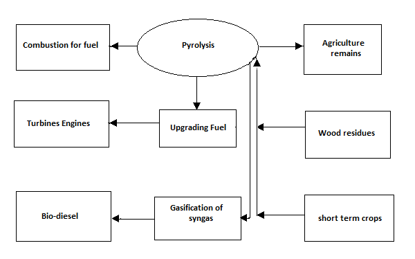
Pyrolysis
Pyrolysis is another form of processing bio-fuels by burning under very high temperatures without oxygen, which could cause complete combustion. This causes irreversible physical and chemical changes. The absence of oxidation or halogenations processes results in a very dense bio-fuel that could be used in combustion, co-combustion or converted to gas.
Slow pyrolysis occurs at about 400oC. It is the process of making solid charcoal.
Fast pyrolysis occurs between 450oC to 600oC and results in organic gas, pyrolysis vapor, and charcoal. The vapor is processed by condensation to liquid form as biooil. This must be done within 1 second to prevent further reaction. The resultant liquid is dark brown liquid denser than wood biomass and has equal content in terms of energy.
Bio-oil has a number of advantages. It is easier to transport, burn, and store. Many kinds of feedstock can be processed through pyrolysis to produce bio-oil.
The diagram given below explains the process in converting energy in to a usable form from bio-fuels through Pyrolysis.
Alcoholic Fermentation
Alcoholic fermentation is the process that converts sugars into cellulose. The process results in ethanol and carbon dioxide as the by-products. This process is considered anaerobic since it takes place in the absence of oxygen. Apart from bread baking and manufacturing alcoholic beverages, this process produces alcoholic fuel. The chemical formula for alcoholic fermentation is given by −
$C_{6}H_{12}O_{6}+yeast\longrightarrow\:2C_{2}H_{5}OH+2CO_{2}$
Sugarcane is the main feedstock for this process especially in dry environments. Corn or sugar bits are used in temperate areas.
Application of Products
The products have the following applications −
Acetone is a product used for production of food additives, dissolving glue, thinning of paint, grease removers and in cosmetic products.
Hydrogen is used as a cooling agent in power industry. It is also used in hydrogen cells for energy production.
Butanol provides better fuel than ethanol. It is also used as an ingredient in paint, cosmetic products, resins, dyes, polymer extractions and in the manufacture of synthetic fiber.
Ethanol is used as fuel, paint component, and an additive in antiseptics. It is also used in alcoholic beverages.
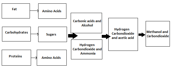
Anaerobic Digestion of Biogas
Anaerobic digestion is the biological process by which organic matter is broken down to produce biogas in the absence of Oxygen. Microorganisms such as Acidogenetic bacteria and acetogens convert the biodegradable matter to biogas. Apart from being a source of energy, it is also a waste deposition method and environmental conservation technique.
The main equation for this conversion that yields carbon dioxide and methane is as follows −
$C_{6}H_{12}O_{6}\longrightarrow\:3CO_{2}+3CH_{4}$
The step-by-step process is explained below −
Step 1 − Breakdown of organic matter to sizable molecules for conversion. This process is known as hydrolysis.
Step 2 − Acidogens act on the decomposed matter converting them into volatile fatty acids (VFAs) alongside ammonia, CO2 and hydrogen sulfide. The process is called acidogenesis.
Step 3 − The VFAs are further broken down into acetic acid, carbon dioxide and hydrogen.
Step 4 − The final stage is the combination of emissions above to produce methanol, carbon dioxide, and water.