- Arduino - Home
- Arduino - Overview
- Arduino - Board Description
- Arduino - Installation
- Arduino - Program Structure
- Arduino - Data Types
- Arduino - Variables & Constants
- Arduino - Operators
- Arduino - Control Statements
- Arduino - Loops
- Arduino - Functions
- Arduino - Strings
- Arduino - String Object
- Arduino - Time
- Arduino - Arrays
- Arduino Function Libraries
- Arduino - I/O Functions
- Arduino - Advanced I/O Function
- Arduino - Character Functions
- Arduino - Math Library
- Arduino - Trigonometric Functions
- Arduino Advanced
- Arduino - Due & Zero
- Arduino - Pulse Width Modulation
- Arduino - Random Numbers
- Arduino - Interrupts
- Arduino - Communication
- Arduino - Inter Integrated Circuit
- Arduino - Serial Peripheral Interface
- Arduino Projects
- Arduino - Blinking LED
- Arduino - Fading LED
- Arduino - Reading Analog Voltage
- Arduino - LED Bar Graph
- Arduino - Keyboard Logout
- Arduino - Keyboard Message
- Arduino - Mouse Button Control
- Arduino - Keyboard Serial
- Arduino Sensors
- Arduino - Humidity Sensor
- Arduino - Temperature Sensor
- Arduino - Water Detector / Sensor
- Arduino - PIR Sensor
- Arduino - Ultrasonic Sensor
- Arduino - Connecting Switch
- Motor Control
- Arduino - DC Motor
- Arduino - Servo Motor
- Arduino - Stepper Motor
- Arduino And Sound
- Arduino - Tone Library
- Arduino - Wireless Communication
- Arduino - Network Communication
Arduino - Pulse Width Modulation
Pulse Width Modulation or PWM is a common technique used to vary the width of the pulses in a pulse-train. PWM has many applications such as controlling servos and speed controllers, limiting the effective power of motors and LEDs.
Basic Principle of PWM
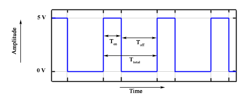
Pulse width modulation is basically, a square wave with a varying high and low time. A basic PWM signal is shown in the following figure.
There are various terms associated with PWM −
On-Time − Duration of time signal is high.
Off-Time − Duration of time signal is low.
Period − It is represented as the sum of on-time and off-time of PWM signal.
Duty Cycle − It is represented as the percentage of time signal that remains on during the period of the PWM signal.
Period
As shown in the figure, Ton denotes the on-time and Toff denotes the off-time of signal. Period is the sum of both on and off times and is calculated as shown in the following equation −
$$T_{total} = T_{on}+T_{off}$$Duty Cycle
Duty cycle is calculated as the on-time of the period of time. Using the period calculated above, duty cycle is calculated as −
$$D = \frac{T_{on}}{T_{on}+T_{off}} = \frac{T_{on}}{T_{total}}$$analogWrite() Function
The analogWrite() function writes an analog value (PWM wave) to a pin. It can be used to light a LED at varying brightness or drive a motor at various speeds. After a call of the analogWrite() function, the pin will generate a steady square wave of the specified duty cycle until the next call to analogWrite() or a call to digitalRead() or digitalWrite() on the same pin. The frequency of the PWM signal on most pins is approximately 490 Hz. On the Uno and similar boards, pins 5 and 6 have a frequency of approximately 980 Hz. Pins 3 and 11 on the Leonardo also run at 980 Hz.
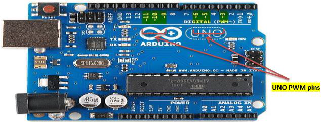
On most Arduino boards (those with the ATmega168 or ATmega328), this function works on pins 3, 5, 6, 9, 10, and 11. On the Arduino Mega, it works on pins 2 - 13 and 44 - 46. Older Arduino boards with an ATmega8 only support analogWrite() on pins 9, 10, and 11.
The Arduino Due supports analogWrite() on pins 2 through 13, and pins DAC0 and DAC1. Unlike the PWM pins, DAC0 and DAC1 are Digital to Analog converters, and act as true analog outputs.
You do not need to call pinMode() to set the pin as an output before calling analogWrite().
analogWrite() Function Syntax
analogWrite ( pin , value ) ;
value − the duty cycle: between 0 (always off) and 255 (always on).
Example
int ledPin = 9; // LED connected to digital pin 9
int analogPin = 3; // potentiometer connected to analog pin 3
int val = 0; // variable to store the read value

void setup() {
   pinMode(ledPin, OUTPUT); // sets the pin as output
}

void loop() {
   val = analogRead(analogPin); // read the input pin
   analogWrite(ledPin, (val / 4)); // analogRead values go from 0 to 1023,
      // analogWrite values from 0 to 255
}
