
Article Categories
- All Categories
-
 Data Structure
-
 Networking
-
 RDBMS
RDBMS
-
 Operating System
-
 Java
Java
-
 MS Excel
-
 iOS
iOS
-
 HTML
HTML
-
 CSS
CSS
-
 Android
-
 Python
-
 C Programming
-
 C++
C++
-
 C#
C#
-
 MongoDB
-
 MySQL
MySQL
-
 Javascript
-
 PHP
PHP
-
 Economics & Finance
I/O-mapped I/O or memory-mapped I/O in 8085 Microprocessor
Before having a discussion regarding the demerits or merits of I/O mapped I/O and memory-mapped I/O, let us have a generic discussion regarding the difference between I/O mapped I/O and memory mapped I/O.
In Memory Mapped Input Output −
We allocate a memory address to an Input-Output device.
Any instructions related to memory can be accessed by this Input-Output device.
The Input-Output device data are also given to the Arithmetic Logical Unit.
Input-Output Mapped Input Output −
We give an Input-Output address to an Input-Output device
Only IN and OUT instructions are accessed by such devices.
The ALU operations are not directly applicable to such Input-Output data.
So as a summary we can mention that −
I/O is any general-purpose port used by processor/controller to handle peripherals connected to it.
I/O mapped I/Os have a separate address space from the memory. So, total addressed capacity is the number of I/Os connected and a memory connected. Separate I/O-related instructions are used to access I/Os. A separate signal is used for addressing an I/O device.
Memory-mapped I/Os share the memory space with external memory. So, total addressed capacity is memory connected only. This is underutilisation of resources if your processor supports I/O-mapped I/O. In this case, instructions used to access I/Os are the same as that used for memory.
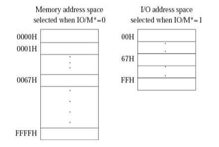
Let's take an example of the 8085 processor. It has 16 address lines i.e. addressing capacity of 64 KB memory. It supports I/O-mapped I/Os. It can address up to 256 I/Os.
If we connect I/Os to it an I/O-mapped I/O then, it can address 256 I/Os + 64 KB memory. And special instructions IN and OUT are used to access the peripherals. Here we fully utilize the addressing capacity of the processor.
If the peripherals are connected in memory mapped fashion, then total devices it can address is only 64K. This is underutilisation of the resource. And only memory-accessing instructions like MVI, MOV, LOAD, SAVE are used to access the I/O devices.
After the discussion stated earlier, it is not possible for us to conclude to which scheme of addressing the Input Output ports is better. Both of them have their advantages and disadvantages. The Intel family of microprocessors like 8085, 8086, 80386, Pentium, and Zilog family of microprocessors like Z-80, Z-8000, etc. provide I/O-mapped I/O facility, in addition to providing memory-mapped I/O. So some I/O ports can be connected as I/O-mapped I/O ports, and some others as memory-mapped I/O ports in an Intel processor-based system. But Motorola family of microprocessors like 6800, 68000, 68020, etc. provide only memory-mapped I/O. Thus, we can say that an Intel processor is better compared with a Motorola processor, as far as addressing of I/O ports is concerned.
After the discussions stated earlier it is not possible for us to conclude to the extent of which scheme of addressing the Input-Output port is better. Both of them have their advantages and disadvantages. The family of microprocessors which belong to the Intel family-like 8085, 8086, 80386, Pentium, and Zilog family of microprocessors like Z-80, Z-8000, etc provide the facility of Input-Output mapping to Input-Output facility. Where in addition, we provide the facility of memory mapped Input Output also In the processor-based system manufactured by Intel. But the family of microprocessors which belong to Motorolla like 6800, 68000, 68020 provides only Memory mapped Input Output. Hence we can conclude that the processor which belong to Intel family is far better compared with the processor of Motorolla as far the addressing of the Input-Output ports is concerned.

7K+ Views
