
Article Categories
- All Categories
-
 Data Structure
-
 Networking
-
 RDBMS
RDBMS
-
 Operating System
-
 Java
Java
-
 MS Excel
-
 iOS
iOS
-
 HTML
HTML
-
 CSS
CSS
-
 Android
-
 Python
-
 C Programming
-
 C++
C++
-
 C#
C#
-
 MongoDB
-
 MySQL
MySQL
-
 Javascript
-
 PHP
PHP
-
 Economics & Finance
Discuss the various Input-Output Instructions in Computer Architecture?
The instructions and data that have to be calculated should be entered into the computer by the various medium. The results should be provided to the user by a medium. The Input/output structure of the computer supports a method to communicate with the external world and prepare the operating frameworks with the data it requires to handle the I/O activity efficiently.
Input-Output Configuration
The figure displays an illustration of the input and output device. The input device is the keyboard and the output device is the printer. The terminals are the keyboard and printer. They send and receive the data consecutively.
The data is alphanumeric and 8-bits in size. The input supported by the keyboard is transfer to the input register INPR. The information is saved in the OUTPR (output register) in the serial order for the printer. The OUTR saves the serial data for the printer.
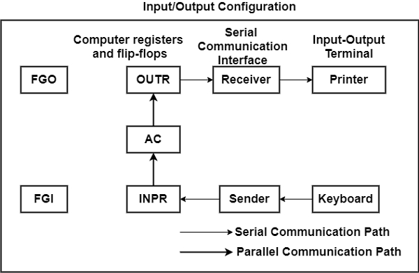
The I/O registers communicate serially with interfaces (keyboard, printer) and parallel with AC.
The sender interface receives data from the keyboard and transfers it to INPR.
The receiver interfaces access the data and address it to the printer.
The INPR holds the 8- bit alphanumeric input data.
FGI defines a 1-bit input flag which is a flip-flop. When the input device receives any new information, the flip flop is set to 1. It is cleared to 0 when information is received through the output device.
The difference between the timing rates of input devices and computers is integrated through the flag. The method is equivalent to the output device and the difference being the transform in control of the data flow.
The output device sets the FGO to 1 after receiving, decoding, and printing the information. FGO in the 0 modes denotes that the device is printing information.
Input/Output Instruction
The I/O devices are given specific addresses. The processor similarly views the I/O operations as memory operations. It concerns commands that include the address for the device.
The I/O instructions are needed for the following objectives −
- It is used to analyzing flag bits.
- It can transfer data to or from the AC register.
- It can controlling interrupts.
The I/O instructions carry the opcode as 1111. They are recognized through the control when D7 = 1 and I=1. The operation to be executed is determined by the different remaining bits.
There are various I/O Instructions which are shown in the table −
| Symbol | Description |
|---|---|
| INP | The INP instruction address the information from the INPR to AC which has 8 low order bits. It also clears the input flag to 0. |
| OUT | It can send the 8 low order bits from AC into output register OUTPR. It also clears the output flag to 0. |
| SKI | These are the status flags. They skip the next instructions when flag = 1, They are primarily branching instructions. |
| SKO | It is similar to SKI. |
| ION | Enables (set) interrupt. |
| IOF | Disables (clear) interrupt. |

16K+ Views
