- UMTS Tutorial
- UMTS - Home
- History of Mobile Communication
- Cellular Concepts
- Cellular Concepts - Introduction
- GSM Architecture
- Cellular Concepts - GSM Radio Link
- Cellular Concepts - Mobility
- Cellular Concepts - GPRS
- Cellular Concepts - EDGE
- UMTS Introduction
- UMTS - A New Network
- UMTS - WCDMA Technology
- UMTS - HSPA Standardization
- UMTS - Objectives
- UMTS - Authentication
- UMTS - Success and Limitations
- UMTS Networks Standardization
- UMTS - 3GPP
- UMTS - Radio Access Network
- UMTS - Evolved Packet Core
- UMTS Protocol Environment
- UMTS - GPRS Tunneling Protocol
- UMTS - Proxy Mobile IPv6
- UMTS - EAP
- UMTS - IKEv2 & MOBIKE
- UMTS - SCTP
- UMTS - NAS Signaling Protocol
- UMTS Useful Resources
- UMTS - Quick Guide
- UMTS - Useful Resources
- UMTS - Discussion
UMTS - Quick Guide
History of Mobile Communication
Wireless communication was a magic to our ancestors but Marconi could initiate it with his wireless telegraph in 1895. Wireless Communication can be classified into three eras.
- Pioneer Era (Till 1920)
- Pre Cellular Era(1920-1979)
- Cellular Era (beyond 1979)
The first commercial mobile telephone system was launched by BELL in St. Louis, USA, in 1946. Few lucky customers got the services. Early mobile systems used single high power transmitters with analog Frequency Modulation techniques to give coverage up to about 50 miles and hence only limited customers could get the service due to this severe constraints of bandwidth.
Cellular Era
To overcome the constraints of bandwidth scarcity and to give coverage to larger sections, BELL lab introduced the principle of Cellular concept. By frequency reuse technique this method delivered better coverage, better utility of available frequency spectrum and reduced transmitter power. But the established calls are to be handed over between base stations while the phones are on move.
Even though the US based BELL lab introduced the cellular principle, the Nordic countries were the first to introduce cellular services for commercial use with the introduction of the Nordic Mobile Telephone (NMT) in 1981.
First Generation Systems
All these systems were analog systems, using FDMA technology. They are also known as First Generation (1G) systems. Different systems came into use based on the cellular principle. They are listed below.
| Year | Mobile System |
|---|---|
| 1981 | Nordic Mobile Telephone(NMT)450 |
| 1982 | American Mobile Phone System(AMPS) |
| 1985 | Total Access Communication System(TACS) |
| 1986 | Nordic Mobile Telephony(NMT)900 |
Disadvantages of 1G systems
- They were analog and hence are were not robust to interference.
- Different countries followed their own standards, which were incompatible.
To overcome the difficulties of 1G, digital technology was chosen by most of the countries and a new era, called 2G, started.
Advantages of 2G
- Improved Spectral Utilization achieved by using advanced modulation techniques.
- Lower bit rate voice coding enabled more users getting the services simultaneously.
- Reduction of overhead in signaling paved way for capacity enhancement.
- Good source and channel coding techniques make the signal more robust to Interference.
- New services like SMS were included.
- Improved efficiency of access and hand-off control were achieved.
| Name of the Systems | Country |
|---|---|
| DAMPS-Digital Advanced Mobile Phone System | North America |
| GSM-Global System for Mobile communication | European Countries and International applications |
| JDC - Japanese Digital Cellular | Japan |
| CT-2 Cordless Telephone–2 | UK |
| DECT-Digital European Cordless Telephone | European countries |
History of GSM
GSM standard is a European standard, which has addressed many problems related to compatibility, especially with the development of digital radio technology.
Milestones of GSM
- 1982 - Confederation of European Post and Telegraph (CEPT) establishes Group Special Mobile.
- 1985 - Adoption of list of recommendation was decided to be generated by the group.
- 1986 - Different field tests were done for radio technique for the common air interface.
- 1987 - TDMA was chosen as the Access Standard. MoU was signed between 12 operators.
- 1988 - Validation of system was done.
- 1989 - Responsibility was taken up by European Telecommunication Standards Institute (ETSI).
- 1990 - First GSM specification was released.
- 1991 - First commercial GSM system was launched.
Frequency Range of GSM
GSM works on four different frequency ranges with FDMA-TDMA and FDD. They are as follows −
| System | P-GSM (Primary) | E-GSM (Extended) | GSM 1800 | GSM 1900 |
|---|---|---|---|---|
| Freq Uplink | 890-915MHz | 880-915MHz | 1710-1785Mhz | 1850-1910MHz |
| Freq Downlink | 935-960MHz | 925-960MHz | 1805-1880Mhz | 1930-1990MHz |
Cellular Concepts - Introduction
The immense potential of conventional telephone cannot be exploited to its maximum due to the limitation imposed by the connecting wires. But this restriction has been removed with the advent of the cellular radio.
Frequency Scarcity Problem
If we use dedicated RF loop for every subscriber, we need larger bandwidth to serve even a limited number of subsc in a single city.
Example
A single RF loop requires 50 kHz B/W; then for one lakh subscribers we need 1,00,000 x 50 kHz = 5 GHz.
To overcome this B/W problem, subscribers have to share the RF channels on need basis, instead of dedicated RF loops. This can be achieved by using multiple access methods FDMA, TDMA, or CDMA. Even then the number of RF channels required to serve the subscribers, works out to be impracticable.
Example
Consider a subs density of 30Sq.Km., Grade of service as 1%, Traffic offered per mobile sub as 30m E. Then number of RF channels required are −
| Radius(km) | Area in Sq.km | Subs | RF Channels |
|---|---|---|---|
| 1 | 3.14 | 100 | 8 |
| 3 | 28.03 | 900 | 38 |
| 10 | 314 | 10000 | 360 |
For 10,000 subs to allot 360 radio channels we need a B/Wof 360 × 50 KHz = 18 MHz. This is practically not feasible.
Cellular Approach
With limited frequency resource, cellular principle can serve thousands of subscribers at an affordable cost. In a cellular network, total area is subdivided into smaller areas called “cells”. Each cell can cover a limited number of mobile subscribers within its boundaries. Each cell can have a base station with a number of RF channels.
Frequencies used in a given cell area will be simultaneously reused at a different cell which is geographically separated. For example, a typical seven-cell pattern can be considered.
Total available frequency resources are divided into seven parts, each part consisting of a number of radio channels and allocated to a cell site. In a group of 7 cells, available frequency spectrum is consumed totally. The same seven sets of frequency can be used after certain distance.
The group of cells where the available frequency spectrum is totally consumed is called a cluster of cells.
Two cells having the same number in the adjacent cluster, use the same set of RF channels and hence are termed as “Co-channel cells”. The distance between the cells using the same frequency should be sufficient to keep the co-channel (co-chl) interference to an acceptable level. Hence, the cellular systems are limited by Co-channel interference.
Hence a cellular principle enables the following.
More efficient usage of available limited RF source.
Manufacturing of every piece of subscriber's terminal within a region with the same set of channels so that any mobile can be used anywhere within the region.
Shape of Cells
For analytical purposes a “Hexagon” cell is preferred to other shapes on paper due to the following reasons.
A hexagon layout requires fewer cells to cover a given area. Hence, it envisages fewer base stations and minimum capital investment.
Other geometrical shapes cannot effectively do this. For example, if circular shaped cells are there, then there will be overlapping of cells.
Also for a given area, among square, triangle and hexagon, radius of a hexagon will be the maximum which is needed for weaker mobiles.
In reality cells are not hexagonal but irregular in shape, determined by factors like propagation of radio waves over the terrain, obstacles, and other geographical constraints. Complex computer programs are required to divide an area into cells. One such program is “Tornado” from Siemens.
Operating Environment
Due to mobility, the radio signals between a base station and mobile terminals undergo a variety of alterations as they travel from transmitter to receiver, even within the same cell. These changes are due to −
- Physical separation of transmitter and receiver.
- Physical environment of the path i.e. terrain, buildings, and other obstacles.
Slow Fading
In free space conditions (or) LOS, RF signal propagation constant is considered as two i.e. r = 2. This is applicable for static radio systems.
In mobile environment, these variations are appreciable and normally ‘r’ is taken as 3 to 4.
Rayleigh Fading
The direct line of sight in mobile environment, between base station and the mobile is not ensured and the signal received at the receiver is the sum of a number of signals reaching through different paths (multipath). Multipath propagation of RF waves is due to the reflection of RF energy from a hill, building, truck, or aero plane etc.; the reflected energy undergoes a phase change also.
If there are 180 out-of phase with direct path signals, they tend to cancel out each other. So the multipath signals tend to reduce the signal strength. Depending upon the location of the transmitter and receiver and various reflecting obstacles along the path length, signal fluctuates. The fluctuations occur fast and it is known as “Rayleigh fading”.
In addition, multipath propagation leads to “pulse widening” and “Inter symbol Interference”.
Doppler Effect
Due to the mobility of the subscriber, a change occurs in the frequency of the received RF signals. Cellular mobile systems use following techniques to counter these problems.
- Channel coding
- Interleaving
- Equalization
- Rake receivers
- Slow frequency hopping
- Antennae diversity
Co-Channel Interference and Cell Separation
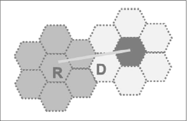
We assume a cellular system having a cell radius “R” and Co-channel distance “D” and the cluster size “N”. Since the cell size is fixed, co-channel interference will be independent of power.
Co-chl interference is a function of “q” = D/R.
Q = Co-chl interference reduction factor.
Higher value of “q” means less interference.
Lower value of “q” means high interference.
“q” is also related to cluster size (N) as q = 3N
q = 3N = D/R
For different values of N, q is −
N = 1 3 4 7 9 12
Q = 1.73 3 3.46 4.58 5.20 6.00
Higher values of “q”
- Reduces co-channel interference,
- Leads to higher value of “N” more cells/cluster,
- Less number of channels/cells,
- Less traffic handling capacity.
Lower values of “q”
- Increases co-channel interference,
- Leads to lower value of “n” fewer cells / cluster,
- More number of channels / cells,
- More traffic handling capacity.
Generally, N = 4, 7, 12.
C/I Calculations and ‘q’
The value of “q” also depends on C/I. “C” is the received carrier power from the desired transmitter and “I” is the co-channel interference received from all the interfering cells. For a seven-cell reuse pattern, the number of co-channel interfering cells shall be six in number.
Loss of signal is proportional to (distance) –r
R – Propagation constant.
c α R-r
R = Radius of cell.
I α 6 D-r
D= Co-channel separation distance
C/I = R – r / 6D –r = 1/6 × Dr / Rr = 1/6 (D/R) r
C/I = 1/6 q r since q = D/R and q r = 6 C/I
Q = [6 × C/I]1/r
Based upon the acceptable voice quality, the value of C/I has been found to be equal to 18 dB.
Assuming,
- A seven-cell reuse pattern
- Omni directional antennae
Value of ‘q’ can be typically around 4.6.
Value r is taken as 3.
This is an ideal condition, considering the distance of the mobile units from the interfering cells to be uniformly equal to ‘D’ in all cases. But practically mobile moves and distance ‘D’ reduces to ‘D-R’ when it reaches the boundary of the cell, and C/I drops to 14.47 dB.
Hence ‘freq’ reuse pattern of 7 is not meeting C/I criteria with omni directional antennae.
If N = 9 (or) 12,
N = 9q = 5.2C/I = 19.78 dB
N = 12q = 6.0C/I = 22.54 dB
Hence, either 9 or 12 cell pattern is to be with omni directional antennae, but traffic handling capacity is reduced. Hence they are not preferred.
In order to use N = 7 (or lower), directional antennas are used in every cell site. A cell having 3 sectors is very popular and will be like the figure shown below.
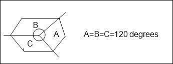
Antenna’s font – back coupling phenomenon reduces number of potential interferers.
For example if N = 7.
With omni directional antennae, number of interfering cells shall be six. With directional antennae & 3 sectors the same is reduced to two. For N = 7 and three sectors, the C/I improves from 14.47 dB to 24.5 dB even in worst conditions. Then C/I meets the requirement of 18dB. For N = 7 and six sectors, the C/I improves to 29 dB.
For Urban applications, N = 4 and a three sector cell is used so that more number of carriers per cell are obtained than N = 7. Also the C/I becomes 20 dB in worst cases.
DAMPS Uses 7/21 cell pattern
GSM Uses 4/21 cell pattern
Advantages of sectoring
- Decrease co-channel interference
- Increase system capacity
Disadvantages of sectoring
- Large number of antennas at the base station.
- Increase in the number of sectors/cell reduces the trunking efficiency
- Sectoring reduces the coverage area, for a particular group of channels.
- Number of ‘Hand offs’ increases.
Hand Off
When the mobile unit travels along a path it crosses different cells. Each time it enters into a different cell associated with f = different frequency, control of the mobile is taken over by the other base station. This is known as ‘Hand off’.
Hand off is decided based on −
- Received signal strength information if it is below a threshold value.
- Carrier to interference ratio is less than 18 dB.
Adjacent Channel Interference
A given cell/sector uses a number of RF channels. Because of imperfect receiver filters, which allow nearby frequencies to leak into pass band, adjacent channel interference takes place.
It can be reduced by keeping the frequency separations between each RF channel in a given cell as large as possible. When the reuse factor is small, this separation may not be sufficient.
A channel separation, by selecting RF frequencies, which are more than 6 channels apart, is sufficient to keep adjacent channel interferences within limits.
For example, in GSM which follows 4/12 pattern, N = 4
Sectors = 3/cell
IA will use RF Carr. 1, 13, 25,………..
IB will use RF Carr 5, 17, 29,…………
IC will use RF Carr. 9, 21, 33,……….. and so on.
Trunking
Cellular radios rely on trunking to accommodate a large number of users in a limited radio spectrum. Each user is allocated a channel on need/per call basis and on termination of the cell, the channel is returned to the common pool of RF channels.
Grade of Service (GOS)
Because of trunking, there is a likelihood that a call is blocked if all the RF channels are engaged. This is called ‘Grade of Service’ “GOS”.
Cellular designer estimates the maximum required capacity and allocates the proper number of RF channels, in order to meet the GOS. For these calculations, ‘ERLANG B’ table is used.
Cell Splitting
When the number of users reaches a saturation in a start-up cell (initial design) and no more spare frequency is available, then the start-up cell is split, usually in four smaller cells and traffic increases by four and more number of subscribers can be served.
After ‘n’ splits, the traffic will be −
T2 = T0 × 42
Power will be reduced −
P2 = P0 – n × 12 db
Hence cell splitting improves the capacity and lowers the transmission power.
Cellular Concepts - GSM Architecture
The GSM network is divided into four major systems −
- Switching System (SS)
- Base Station System (BSS)
- Mobile Station (MS)
- Operation and Maintenance Center(OMC)
The switching system also called as Network and Switching System (NSS), is responsible for performing call processing and subscriber-related functions. The switching system includes the following functional units −
- Mobile Switching Center
- Home Location Register
- Visitor Location Register
- Equipment Identity Register
- Authentication Center
Mobile Switching Center
Mobile Switching Center (MSC) performs all the switching functions for all mobile stations, located in the geographic area controlled by its assigned BSSs. Also, it interfaces with PSTN, with other MSCs, and other system entities.
Functions of MSC
Call handling that copes with the mobile nature of subscribers considering Location Registration, Authentication of subscribers and equipment, Handover and Prepaid service.
Management of required logical radio link channel during calls.
Management of MSC-BSS signaling protocol.
Handling location registration and ensuring interworking between mobile station and VLR.
Controls inter-BSS and inter-MSC hand overs.
Acting as a gateway MSC to interrogate HLR. The MSC which is connected to the PSTN/ISDN network is called as GMSC. This is the only MSC in the network connected to the HLR.
Standard functions of a switch like charging.
Home Location Register (HLR)
Home location register contains −
- The identity of mobile subscriber called International Mobile Sub Identity (IMSI).
- ISDN directory number of mobile station.
- Subscription information on services.
- Service restrictions.
- Location Information for call routing.
One HLR per GSM network is recommended and it may be a distributed database. Permanent data in HLR is changed by the man-machine interface. Temporary data like location information changes dynamically in HLR.
Visitor Location Register (VLR)
The VLR is always integrated with the MSC. When a mobile station roams into a new MSC area, the VLR connected to that MSC would request data about the mobile station from the HLR. Later, if the mobile station makes a call, the VLR has the information needed for call setup without having to interrogate the HLR each time. VLR contains information like the following −
- Identity of mobile sub,
- Any temporary mobile sub identity,
- ISDN directory number of the mobile,
- A directory number to route the call to the roaming station,
- Part of the data of HLR for the mobiles that are currently located in MSC service area.
Equipment Identity Register
Equipment Identity Register consists of identity of mobile station equipment called International Mobile Equipment Identity (IMEI), which may be valid, suspect, and prohibited. When a mobile station accesses the system, the equipment validation procedure is evoked before giving the services.
The information is available in the form of three lists.
White List- The terminal is allowed to connect to the Network.
Grey List- The terminal is under observation from the network for the possible problems.
Black List- The terminals reported as stolen are not type approved. They are not allowed to connect to the network. EIR informs the VLR about the list, the particular IMEI is in.
Authentication Centre
It is associated with an HLR. It stores an Identity key called Authentication key (Ki) for each Mobile subscriber. This key is used to generate the authentication triplets.
- RAND (Random Number),
- SRES (Signed Response) -To authenticate IMSI,
- Kc (Cipher Key) - To cipher communication over the radio path between the MS and the network.
Operation and Maintenance Centre (OMC)
It is the functional entity through which the network operator can monitor and control the system by performing the following functions −
- Software installation
- Traffic management
- Performance data analysis
- Tracing of subscribers and equipment
- Configuration management
- Subscriber administration
- Management of mobile equipment
- Management of charging and billing
Base Station System (BSS)
BSS connects the MS and the NSS. It is composed of the following −
- Base Transceiver Station (BTS) also called Base Station.
- Base Station Controller (BSC).
BTS and BSC communicate across the standardized Abis interface. BTS is controlled by BSC and one BSC can have many BTS under its control.
Base Transceiver Station (BTS)
BTS houses the radio transceivers and handles the radio-link protocols with the Mobile Station. Each BTS comprises of radio transmission and reception devices including antenna, signal processors, etc. Each BTS can support 1 to 16 RF carriers. The parameters differentiating the BTSs are Power level, antenna height, antenna type and number of carriers.
Functions of BTS
It is responsible for Time and Frequency synchronization.
The process of channel coding, Encryption, Multiplexing and modulation for trans-direction and reverse for reception are to be carried out.
It has to arrange for transmission in advance from the mobiles depending upon their distance from BTS (Timing Advance).
It has to detect Random access requests from mobiles, measure and monitor the radio channels for power control and handover.
Base Station Controller
BSC manages the radio resources for one or a group of BTSs. It handles radio-channel setup, frequency hopping, handovers, and control of the RF power levels. BSC provides the time and frequency synchronization reference signals broadcast by its BTSs. It establishes connection between the mobile station and the MSC. BSC is connected via interfaces to MSC, BTS and OMC.
Mobile Station
It refers to the terminal equipment used by the wireless subscribers. It consists of −
- SIM -Subscriber Identity Module
- Mobile Equipment
SIM is removable and with appropriate SIM, the network can be accessed using various mobile equipments.
The equipment identity is not linked to the subscriber. The equipment is validated separately with IMEI and EIR. The SIM contains an integrated circuit chip with a microprocessor, random access memory (RAM) and read only memory (ROM). SIM should be valid and should authenticate the validity of MS while accessing the network.
SIM also stores subscriber related information like IMSI, cell location identity etc.
Functions of Mobile Station
- Radio transmission and reception
- Radio channel management
- Speech encoding/decoding
- Radio link error protection
- Flow control of data
- Rate adaptation of user data to the radio link
- Mobility management
Performance measurements up to a maximum of six surrounding BTSs and reporting to the BSS, MS can store and display short received alphanumeric messages on the liquid crystal display (LCD) that is used to show call dialing and status information.
There are five different categories of mobile telephone units specified by the European GSM system: 20W, 8W, 5W, 2W, and 0.8W. These correspond to 43-dBm, 39-dBm, 37-dBm, 33-dBm, and 29-dBm power levels. The 20-W and 8-W units (peak power) are either for vehicle-mounted or portable station use. The MS power is adjustable in 2-dB steps from its nominal value down to 20mW (13 dBm). This is done automatically under remote control from the BTS.
Transcoders
Transcoders are a network entities inserted to interface the MSC side to Mobile side. The voice coding rate on the PSTN side is 64Kbps, and in GSM over the air the voice is coded as 13Kbps. To reduce the data rate over the air interface and to reduce the loading of the terrestrial link (4 : 1), transcoders are introduced at an appropriate place, mostly with MSC.
The transcoder is the device that takes 13-Kbps speech or 3.6/6/12-Kbps data multiplexes and four of them to convert into standard 64-Kbps data. First, the 13 Kbps or the data at 3.6/6/12 Kbps are brought up to the level of 16 Kbps by inserting additional synchronizing data to make up the difference between a 13-Kbps speech or lower rate data and then four of them are combined in the transponder to provide 64 Kbps channel within the BSS. Four traffic channels can then be multiplexed in one 64-Kpbs circuit. Thus the TRAU output data rate is 64 Kbps.
Then, up to 30 such 64-Kpbs channels are multiplexed onto a 2.048 Mbps if a CEPT1 channel is provided on the A-bis interface. This channel can carry up to 120-(16x 120) traffic and control signals. Since the data rate to the PSTN is normally at 2 Mbps, which is the result of combining 30- by 64-Kbps channels, or 120- Kbps by 16-Kpbs channels.
Other Network Elements
Other network elements include components such as SMS Service Centre, Voice Mail Box, and SMS Flow.
SMS Service Centre
It interfaces with MSC having interworking functionality to provide Short Message Service (SMS) to mobile subscribers. SMS can be destined to fax machine, PC on the internet or another MS. The location of the recipient MS is queried by MSC and delivered.
Voice Mail Box
When the mobile subscriber is not in a position to answer the incoming calls due to busy/out of service area, then the call gets diverted to a mail box which has already been activated by the subscriber. For this, a separate connectivity has been established from MSC. The subscriber will be alerted through SMS later and can retrieve the message.
SMS Flow
When a user sends an SMS, the request is placed via the MSC.
The MSC forwards the SMS to the SMSC where it gets stored.
The SMSC queries the HLR to find out where the destination mobile is and forwards the message to the destination MSC if the destination mobile is available.
If the mobile is not available the message gets stored in the current SMSC itself. In most installations if a mobile is not available for SMS delivery the SMSC does not retry. Instead, the destination MSC informs the SMSC when the mobile comes back in range. SMS handling is a store and forward operation unlike USSD.
SMS has got a validity period for which it will wait for the destination mobile to be available. After that time the SMSC will delete the message. The validity period can be set by the user. Normal validity is 1 day.
Cellular Concepts - GSM Radio Link
BTS and MS are connected through radio links and this air interface is called the Um. A radio wave is subject to attenuation, reflection, Doppler shift, and interference from other transmitter. These effects cause loss of signal strength and distortion which impacts the quality of voice or data. To cope with the harsh conditions, GSM makes use of an efficient and protective signal processing. Proper cellular design must ensure that sufficient radio coverage is provided in the area.
The signal strength variation for mobile is due to the different types of signal strength fading. There are two types of signal strength variations.
Macroscopic Variations − Due to the terrain contour between BTS and MS. The fading effect is caused by shadowing and diffraction (bending) of the radio waves.
Microscopic variations − Due to multipath, Short-term or Rayleigh fading. As the MS moves, radio waves from many different path will be received.
Rayleigh Fading
Rayleigh Fading or Macroscopic Variations can be modeled as the addition of two components that make up the path loss between the mobile and the base station. The first component is the deterministic component (L) that adds loss to the signal strength as the distance (R) increases between the base and the mobile. This component can be written as −
L = 1/Rn
Where n is typically 4. The other macroscopic component is a Log normal random variable which takes into account the effects of shadow fading caused by variations in terrain and other obstructions in the radio path. Local mean value of path loss = deterministic component + log normal random variable.
Microscopic Variations or Rayleigh Fading occurs as the mobile moves over short distances compared to the distance between mobile and base. These short term variations are caused by signal scattering in the vicinity of the mobile unit say by a hill, a building, or traffic. This leads to many different paths that are followed between the transmitter and the receiver (Multipath Propagation). The reflected wave is altered in both phase and amplitude. The signal may effectively disappear if the reflected wave is 180 degree out of phase with the direct path signal. The partial out of phase relationships among multiple received signal produce smaller reduction in received signal strength.
Effects of Rayleigh Fading
Reflection and multipath propagation can cause positive and negative effects.
Transmitting/Receiving Processes
There are two major processes involved in transmitting and receiving information over a digital radio link, coding, and modulation.
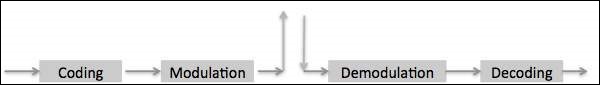
Coverage Extension
Multipath propagation allows radio signals to reach behind hills and buildings and into tunnels. Constructive and destructive interference signals received through multi paths may add together or destroy each other.
Coding
Coding is the information processing that involves preparing the basic data signals so that they are protected and put in a form that the radio link can handle. Generally the coding process includes the Logical EXclusive OR (EXOR). Coding is included in −
- Speech coding or Trans coding
- Channel coding or Forward Error Correction coding
- Interleaving
- Encryption
Burst Formatting
Human speech is band limited between 300Hz to 3400Hz and undergoes Frequency Modulation in analog systems. In digital fixed PSTN systems band limited speech is sampled at the rate of 8KHz and each sampled is encoded into 8 bits leading to 64Kbps (PCM A-Law of encoding). Digital cellular radio cannot handle the high bit rate used for PSTN systems. Smart techniques for signal analysis and processing have been developed for reduction of the bit rate.
Speech Properties
Human speech can be distinguished in elementary sounds (Phonemes). Depending on the language, there are 30 to 50 different phonemes. The human voice is able to produce up to 10 phonemes per second, so that about 60 bit/s are required to transfer the speech. However, all individual features and intonations would disappear. To preserve the individual features, the real amount of information to be sent is a number of times higher, but still a fraction of the 64 Kbit/s used for PCM.
Based upon the phoneme production mechanism of the human organs of speech, a simple speech production model can be made. It appears that during a short time interval of 10-30 ms, the model parameters like pitch-period, voiced/unvoiced, amplification gain, and filter parameters remain about stationary (quasi stationary). The advantage of such a model is the simple determination of the parameters by means of linear prediction.
Speech Coding Techniques
There are 3 classes of speech coding techniques
Waveform Coding − Speech is transmitted as good as possible in wave form coding. PCM is an example of waveform coding. Bit rate ranges from 24 to 64kbps and the quality of speech is good and the speaker can be recognized easily.
Parameter Coding − Only a very limited quantity of information is sent. A decoder built up according to the speech production model will regenerate the speech at the receiver. Only 1 to 3kbps is required for the speech transmission. The regenerated speech is intelligible but it suffers from noise and often the speaker cannot be recognized.
Hybrid Coding − Hybrid Coding is a mix of waveform coding and parameter coding. It combines the strong points of both techniques and GSM uses a hybrid coding technique called RPE-LTP (Regular Pulse Excited-Long Term Prediction) resulting in 13Kbps per voice channel.
Speech Coding in GSM (Transcoding)
The 64kbits/s PCM transcoded from the standard A-law quantized 8bits per sample into a linearly quantized 13bits per sample bit stream that correspond to a 104kbits/s bit rate. The 104kbits/s stream is fed into the RPE-LTP speech encoder which takes the 13 bits samples in a block of 160 samples (every 20ms). RPE-LTP encoder produces 260bits in every 20 ms, resulting in a bit rate of 13kbits/s. This provides a speech quality acceptable for mobile telephony and comparable with wireline PSTN phones. In GSM 13Kbps speech coding is called full rate coders. Alternatively half rate coders (6.5Kbps) are also available to enhance the capacity.
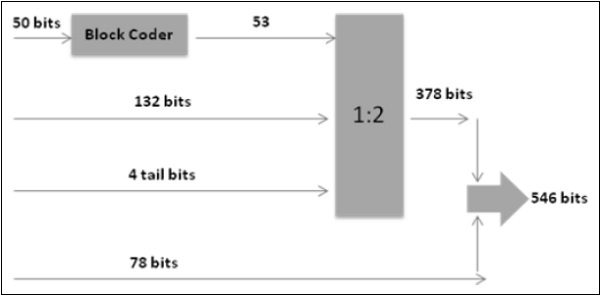
Channel Coding /Convolutional Coding
Channel coding in GSM uses the 260 bits from speech coding as input to channel coding and outputs 456 encoded bits. Out of the 260 bits produced by RPE-LTP speech coder, 182 are classified as important bits and 78 as unimportant bits. Again 182 bits are divided into 50 most important bits and are block coded into 53 bits and are added with 132 bits and 4 tail bits, totaling to 189 bits before undergoing 1:2 convolutional coding, converting 189 bits into 378 bits. These 378 bits are added with 78 unimportant bits resulting in 456 bits.
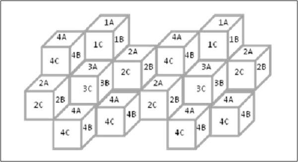
Interleaving - First Level
The channel coder provides 456 bits for every 20ms of speech. These are interleaved, forming eight blocks of 57 bits each, as shown in figure below.
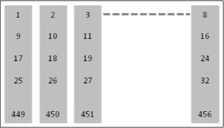
In a normal burst to blocks of 57 bits can be accommodated and if 1 such burst is lost there is a 25% BER for the entire 20ms.
Interleaving - Second Level
A Second level of interleaving has been introduced to further reduce the possible BER to 12.5%. Instead of sending two blocks of 57 bits from the same 20 ms of speech within one burst, a block from one 20ms and a block from next sample of 20ms are sent together. A delay is introduced in the system when the MS must wait for the next 20ms of speech. However, the system can now afford to lose a whole burst, out of the eight, as the loss is only 12.5% of the total bits from each 20ms speech frame. 12.5% is the maximum loss level that a channel decoder can correct.
Encryption /Ciphering
The purpose of Ciphering is to encode the burst so that it may not be interpreted by any other devices than the receiver. The Ciphering algorithm in GSM is called the A5 algorithm. It does not add bits to the burst, meaning that the input and output to the Ciphering process is the same as the input: 456 bits per 20ms. Details about Encryption are available under the special features of GSM.
Multiplexing (Burst Formatting)
Every transmission from mobile/BTS must include some extra information along with basic data. In GSM, a total of 136 bits per block of 20ms are added bringing the overall total to 592 bits. A guard period of 33 bits is also added bringing 625 bits per 20ms.
Modulation
Modulation is the processing that involves the physical preparation of the signal so that the information can be transported on an RF carrier. GSM uses Gaussian Minimum Shift Keying technique (GMSK). Carrier frequency is shifted by +/- B/4, where B=Bit rate. However using the Gaussian filter, reduces the bandwidth to 0.3 instead of 0.5.
Special Features of GSM
Listed below are the special features of GSM that we are going to discuss in the following sections −
- Authentication
- Encryption
- Time Slot Staggering
- Timing Advance
- Discontinuous transmission
- Power Control
- Adoptive equalization
- Slow Frequency Hopping
Authentication
Since the air interface is vulnerable to fraudulent access, it is necessary to employ the authentication before extending the services to a subscriber. Authentication is built around the following notions.
Authentication Key (Ki) resides only in two places, SIM card and Authentication Center.
Authentication Key (Ki) is never transmitted over air. It is virtually impossible for unauthorized individuals to obtain this key to impersonate a given mobile subscriber.
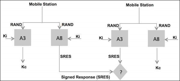
Authentication Parameters
The MS is authenticated by the VLR with a process that uses three parameters −
RAND which is completely random number.
SRES which is an authentication signed response. It is generated by applying an authentication algorithm (A3) to RAND and Ki.
Kc which is cipher key. The Kc parameter generated by applying the cipher key generation algorithm (A8) to RAND and Ki.
These parameters (named an authentication triplet) are generated by the AUC at the request of the HLR to which the subscriber belongs. The algorithms A3 and A8, are defined by the PLMN operator and are executed by the SIM.
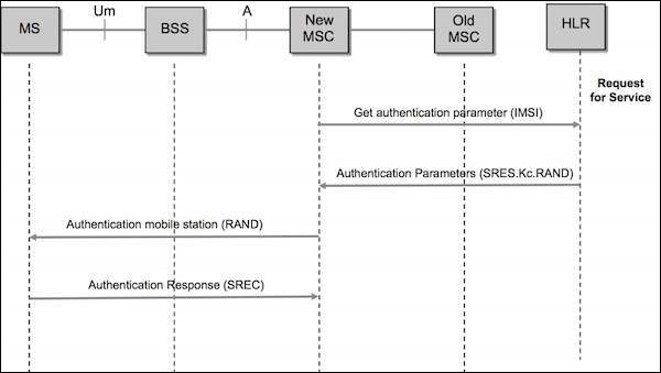
Steps in Authentication Phase
The new VLR sends a request to the HLR/AUC (Authentication Center) requesting the "authentication triplets" (RAND, SRES, and Kc) available for the specified IMSI.
The AUC using the IMSI, extracts the subscribers authentication key (Ki).The AUC then generates a random number (RAND), applies the Ki and RAND to both the authentication algorithm (A3) and the cipher key, generation algorithm (A8) to produce an authentication Signed Response (SRES) and a Cipher Key (Kc). The AUC then returns an authentication triplet: RAND, SRES and Kc to the new VLR.
The MSC/VLR keeps the two parameters Kc and SRES for later use and then sends a message to the MS. The MS reads its Authentication Key (Ki) from the SIM, applies the received random number (RAND) and Ki to both its authentication algorithm (A3) and Cipher key generation Algorithm (A8) to produce an Authentication Signed Response (SRES) and Cipher key (Kc). The MS saves Kc for later, and will use Kc when it receives command to cipher the channel.
The MS returns the generated SRES to the MSC/VLR. The VLR compares the SRES returned from the MS with the expected SRES received earlier from the AUC. If equal, the mobile passes authentication. If unequal, all signaling activities will be aborted. In this scenario, we will assume that authentication is passed.
Encryption/Ciphering
Data is encrypted at the transmitter side in blocks of 114 bits by taking 114-bit plain text data bursts and performing an EXOR (Exclusive OR) logical function operation with a 114-bit cipher block.
The decryption function at the receiver side is performed by taking the encrypted data block of 114 bits and going through the same "exclusive OR" operation using the same 114-bit cipher block that was used at the transmitter.
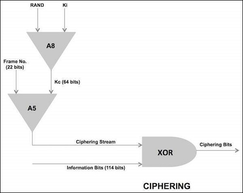
The cipher block used by both ends of transmission path for a given transmission direction is produced at the BSS and MS by an encryption algorithm called A5. The A5 algorithm uses a 64-bit cipher key (Kc), produced during the authentication process during call setup and the 22-bit TDMA frame number (COUNT) which takes decimal values from 0 through 2715647, and has a repetition time of 3.48 hours (hyper frame interval).The A5 algorithm actually produce two cipher blocks during each TDMA period. One path for the uplink path and the other for the downlink path.
Time Slot Staggering
Time slot staggering is the principle of deriving the time slot organization of uplink from the time slot organization of the downlink. A particular time slot of the uplink is derived from the downlink by shifting the downlink time slot number by three.
Reason
By shifting three time slots, the mobile station avoids the ‘transmit and receive’ processes simultaneously. This allows an easier implementation of the mobile station; the receiver in the mobile station does not need to be protected from the transmitter of the same mobile station. Typically a mobile station will receive during one time slot, and then shifts in frequency by 45 MHz for GSM-900 or 95 MHz for GSM-1800 to transmit sometime later. This implies that there is one time base for downlink and one for uplink.
Timing Advance
Timing Advance is the process of transmitting the burst to the BTS (the timing advance) early, to compensate for the propagation delay.
Why is it Needed?
It is required because of the time division multiplexing scheme used on the radio path. The BTS receives signals from different mobile stations very close to each other. However when a mobile station is far from the BTS, the BTS must deal with the propagation delay. It is essential that the burst received at the BTS fits correctly into time slot. Otherwise the bursts from the mobile stations using adjacent time slots could overlap, resulting in a poor transmission or even in loss of communication.
Once a connection has been established, the BTS continuously measures the time offset between its own burst schedule and the reception schedule of the mobile station burst. Based on these measurements, the BTS is able to provide the mobile station with the required timing advance via the SACCH. Note that timing advance is derived from the distance measurement which is also used in the handover process. The BTS sends a timing advance parameter according to the perceived timing advance to each mobile station. Each of the mobile station then advances its timing, with the result that signals from the different mobile stations arriving at BTS, and are compensated for propagation delay.
Time Advance Process
A 6 bit number indicates how many bits the MS must advance its transmission. This time advance is TA.
The 68.25 bit long GP (guard period) of the access burst provides the required flexibility to advance the transmission time.
The time advance TA can have a value between 0 and 63 bits long, which corresponds to a delay of 0 to 233 micro second. For instance the MS at 10 km away from the BTS must start transmitting 66 micro second earlier to compensate for the round trip delay.
The maximum mobile range of 35Km is rather determined by the timing advance value than by the signal strength.
Cellular Concepts - Mobility Management
The mobile station attempts to find a suitable cell by passing through the list in descending order of received signal strength, the first BCCH channel, which satisfies a set of requirements it has selected.
Cell Selection Criteria
The requirements that a cell must satisfy before a mobile station can receive service from it are −
It should be a cell of the selected PLMN. The mobile station checks whether the cell is part of the selected PLMN.
It should not be "barred". The PLMN operator may decide not to allow mobile stations to access certain cells. These cells may, for example only be used for handover traffic. Barred cell information is broadcast on the BCCH to instruct mobile stations not to access these cells.
The radio path loss between the mobile station and the selected BTS must be above a threshold set by the PLMN operator.
If no suitable cell is found then the MS enters a "limited service" state in which it can only make emergency calls.
Call to an Active Mobile Station
As an active mobile station (MS) moves in the coverage area of a public land mobile network (PLMN), it reports its movements so that it can be located as needed, using the update procedure locations. When a mobile services switching center (MSC) in the network needs to establish a call to a mobile station operating in its flow area, following things occur −
A page message its broadcast which contains the identification code of the MS. Not every Base Station Controller (BSC) in the network is requested to transmit the page message. The broadcast is limited to a cluster of radio cells that together form a location area. The last reported position of the MS identifies the location area to be used for the broadcast.
The MS monitors the page message transmitted by the radio cell in which it is located and, on detecting its own identification code, responds by transmitting a page response message to the Base Transceiver Station (BTS).
Communication is then established between the MSC and the MS via BTS that received the page response message.
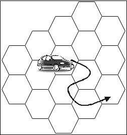
Location Update
Case 1 − Location never updates.
If location never updates the implementation for location update, cost becomes zero. But we have to page every cell for locating the MS and this procedure will not be cost effective.
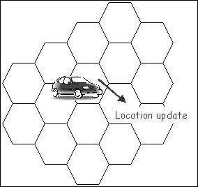
Case 2 − Location update is implemented.
Location updates are taking place as per the requirements of the network, may be time or movement or distance based. This procedure involves high cost, but we have to page single cell or few cells only for locating the MS and this procedure will be cost effective.
Network Configuration
The configuration of a Public Land Mobile Network (PLMN) is designed so that active mobile station moving in the network area is still able to report its position. A network consists of different areas −
- PLMN area
- Location area
- MSC area
- PLMN Area
A PLMN area is the geographical area in which land mobile communication services are provided to the public by a particular PLMN operator. From any position within a PLMN area, the mobile user can set up calls to another user of the same network, or to a user of another network. The other network may be a fixed network, another GSM PLMN, or another type of PLMN. Users of the same PLMN or users of other networks can also call a mobile user who is active in the PLMN area. When there are several PLMN operators, the geographical areas covered by their networks may overlap. The extent of a PLMN area is normally limited by national borders.
Location Area
To eliminate the need for network-wide paging broadcasts, the PLMN needs to know the approximate positions of the MSs that are active within its coverage area. To enable the approximate positions of any MS to be represented by a single parameter, the total area covered by the network is divided into location areas. A Location Area (LA) is a group of one or more radio cells. This group fulfills the following requirements −
BTSs in one location area may be controlled by one or more BSCs.
BSCs those serve the same location area are always connected to the same MSC.
Radio cells with BTSs controlled by a common BSC can lie in different location areas.
Location Area Identity
Every radio transmitter in the PLMN broadcast, via a control channel BCCH, a Location Area Identity (LAI), code to identify the location area that it serves. When an MS is not engaged in a call, it automatically scans the BCCH transmitted by the base stations in the locality and selects the channel that is delivering the strongest signal. The LAI code broadcast by the selected channel identifies the location area in which the MS is currently situated. This LAI code is stored in the Subscriber Identity Module (SIM) of the mobile equipment.
As the MS moves through the network area, the signal received from the selected control channel gradually diminishes in strength until it is no longer the strongest. At this point the MS re-tunes to the channel that has become dominant and examines the LAI code that it is broadcasting. If the received LAI code differs from that stored on the SIM, then the MS has entered another location area and initiates a location update procedure to report the change to the MSC. At the end of the procedure, the LAI code in the SIM is also updated.
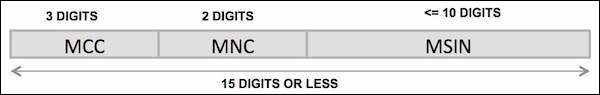
Location Area Identity Format
It is a Location Area Identity (LAI) code to identify the location area in a PLMN. The LAI code has three components −
Mobile Country Code (MCC)
The MCC is a 3-digit code that uniquely identifies the country of domicile of the mobile subscriber (for example, India 404). It is assigned by the ITU-T.
Mobile Network Code (MNC)
The MNC is a 2-digit code (3-digit code for GSM-1900) that identifies the home GSM PLMN of the mobile subscriber. If more than one GSM PLMN exists in a country, a unique MNC is assigned to each of them. It is assigned by the government of each country. (For example Cell one, Chennai 64).
Location Area Code (LAC)
The LAC component identifies a location area within a PLMN; it has a fixed length of 2 octets and can be coded using hexadecimal representation. It is assigned by an operator.
MSC areas
An MSC area is a region of the network in which GSM operations are controlled by a single MSC. An MSC area consists of one more location areas. The boundary of an MSC area follows the external boundaries of the location areas on its periphery. Consequently, a location area never spans beyond the boundary of an MSC area.
VLR area
A VLR area is region of the network that is supervised by a single Visitor Location Register (VLR). In theory, a VLR area may consist of one more MSC areas. In practice, however the functions of the VLR are always integrated with those of the MSC so that the terms "VLR area" and "MSC area" have become synonymous.
Location Related Databases
Two databases are used by Location Management to store MS location related data.
- Visitor Location Register(VLR)
- Home Location Register(HLR)
Visitor Location Register
A VLR contains a data record for each of the MS that are currently operating in its area. Each record contains a set of subscriber identity codes, related subscription information, and a Location Area Identity (LAI) code. This information is used by the MSC when handling calls to or from an MS in the area. When an MS moves from one area to another, the responsibility for its supervision passes from one VLR to another. A new data record is created by the VLR that has adopted the MS, and the old record is deleted. Provided that aninter-working agreement exists between the network operators concerned, data transaction can cross both network and national boundaries.
Home Location Register
The HLR contains information relevant to mobile subscribers who are fee-paying customers of the organization that operates the PLMN.
The HLR stores two types of information −
Subscription Information
The subscription information includes the IMSI and directory number allocated to the subscriber, the type of services provided and any related restrictions.
Location Information
The location information includes the address of the VLR in the area where the subscribers MS is currently located and the address of the associated MSC.
The location information enables incoming calls to be routed to the MS. The absence of this information indicates that the MS is inactive and cannot be reached.
When an MS moves from one VLR area to another, the location information in the HLR is updated with the new entry for the MS, using subscription data copied from the HLR. Provided that an inter-working agreement exists between the network operators, concerned data transactions can move across both network and national boundaries.
Types of Identification Numbers
During the performance of the location update procedure and the processing of a mobile call different types of numbers are used −
- Mobile Station ISDN Number(MSISDN)
- Mobile Subscriber Roaming Number(MSRN)
- International Mobile Subscriber Identity(IMSI)
- Temporary Mobile Subscriber Identity(TMSI)
- Local Mobile Station Identity(LMSI)
Each number is stored in the HLR and/or VLR.
Mobile Station ISDN Number
The MSISDN is the directory number allocated to the mobile subscriber. It is dialed to make a telephone call to the mobile subscriber. The number consists of Country Code (CC) of the country in which the mobile station is registered (e.g. India 91), followed by national mobile number which consists of Network Destination Code (NDC) and Subscriber Number (SN). An NDC is allocated to each GSM PLMN.
The composition of the MSISDN is such that it can be used as a global title address in the Signaling Connection Control Part (SCCP) for routing message to the HLR of the mobile subscriber.
Mobile Station Roaming Number
The MSRN is the number required by the gateway MSC to route an incoming call to an MS that is not currently under the control of the gateway MSISDN. Using a mobile, terminated call is routed to the MSC gateway. Based on this, MSISDN gateway MSC requests for a MSRN to route the call to the current visited MSC International Mobile Subscriber Identity (IMSI).
An MS is identified by its IMSI. The IMSI is embedded in the SIM of the mobile equipment. It is provided by the MS anytime it accesses the network.
Mobile Country Code (MCC)
The MCC component of the IMSI is a 3-digit code that uniquely identifies the country of the domicile of the subscriber. It is assigned by the ITU-T.
Mobile Network Code (MNC)
The MNC component is a 2-digit code that identifies the home GSM PLMN of the mobile subscriber. It is assigned by the government of each country. For GSM-1900 a 3-digit MNC is used.
Mobile Subscriber Identification Number (MSIN)
The MSIN is a code that identifies the subscriber within a GSM PLMN. It is assigned by the operator.
Temporary Mobile Subscriber Identity (TMSI)
The TMSI is an identity alias which is used instead of the IMSI when possible. The use of a TMSI ensures that the true identity of the mobile subscriber remains confidential by eliminating the need to transfer a non ciphered IMSI code over a radio link.
A VLR allocates a unique TMSI code to each mobile subscriber that is operating in its area. This code which is only valid within the area supervised by the VLR is used to identify the subscriber, in messages to and from the MS. When a change of location area also involves a change of VLR area, a new TMSI code is allocated and communicated to the MS. The MS stores the TMSI on its SIM. The TMSI consists of four octets.
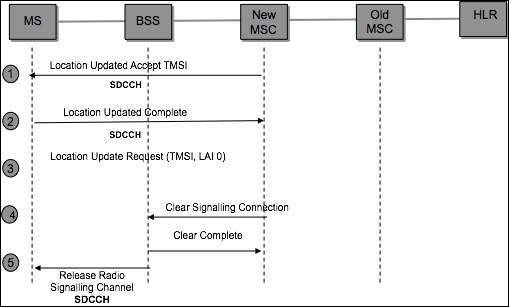
Location Update Scenario
In the following location update scenario, it is assumed that an MS enters a new location area that is under control of a different VLR (referred to as the "new VLR") than the one where the MS is currently registered (referred to as the "old VLR"). The following diagram shows the steps of the mobile location update scenario.
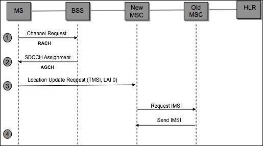
The MS enters a new cell area, listens to the Location Area Identity (LAI) being transmitted on the broadcast channel (BCCH), and compares this LAI with the last LAI (stored in the SIM) representing the last area where the mobile was registered.
The MS detects that it has entered a new Location Area and transmits a Channel Request message over the Random Access Channel (RACH).
Once the BSS receives the Channel Request message, it allocates a Stand-alone Dedicated Control Channel (SDCCH) and forwards this channel assignment information to the MS over the Access Grant Channel (AGCH). It is over the SDCCH that the MS will communicate with the BSS and MSC.
The MS transmits a location update request message to the BSS over the SDCCH. Included in this message are the MS Temporary Mobile Subscriber Identity (TMSI) and the old Location Area Subscriber (old LAI). The MS can identify itself either with its IMSI or TMSI. In this example, we will assume that the mobile provided a TMSI. The BSS forwards the location update request message to the MSC.
The VLR analyses the LAI supplied in the message and determines that the TMSI received is associated with a different VLR (old VLR). In order to proceed with the registration the IMSI of the MS must be determined. The new VLR derives the identity of the old VLR by using the received LAI, supplied in the location update request message. It also requests the old VLR to supply the IMSI for a particular TMSI.
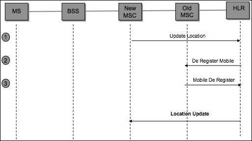
Location Update Scenario-Update HLR/VLR is a point where we are ready to inform the HLR that the MS is under control of a new VLR and that the MS can be de-registered from the old VLR. The steps in update HLR/VLR phase are −
The new VLR sends a message to the HLR informing it that the given IMSI has changed locations and can be reached by routing all incoming calls to the VLR address included in the message.
The HLR requests the old VLR to remove the subscriber record associated with the given IMSI. The request is acknowledged.
The HLR updates the new VLR with the subscriber data (mobiles subscribers’ customer profile).
Steps in TMSI Reallocation Phase
The MSC forwards the location update accept message to the MS. This message includes the new TMSI.
The MS retrieves the new TMSI value from the message and updates its SIM with this new value. The mobile then sends an update complete message back to the MSC.
The MSC requests from the BSS, that the signaling connection be released between the MSC and the MS.
The MSC releases its portion of the signaling connection when it receives the clear complete message from the BSS.
The BSS sends a "radio resource" channel release message to the MS and then free up the Stand-alone Dedicated Control Channel (SDCCH) that was allocated previously. The BSS then informs the MSC that the signaling connection has been cleared.
Location Update Periodicity
Location Update automatically takes place when the MS changes its LA. A lot of location updates may be generated if a user crosses LA boundary frequently. If the MS remains in the same LA, Location Update may take place based on time/movement/distance, as defined by the network provider.
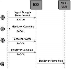
Hand Over
This is the process of automatically switching a call in progress from one traffic channel to another to neutralize the adverse effects of the user movements. Hand over process will be started only if the power control is not helpful anymore.
The Hand Over process is MAHO (Mobile Assisted Hand Over). It starts with the Down Link Measurements by the MS (Strength of the signal from BTS, Quality of the signal from BTS). MS can measure the signal strength of the 6 best neighboring BTS downlink (candidate list).
Hand Over Types
There are two types of Hand Over −
-
Internal or Intra BSS Handover
Intra-cell hand over
Inter cell hand over
-
External or Inter BSS Hand over
Intra-MSC hand over
Inter MSC hand over
Internal handover is managed by the BSC and external handover by MSC.
The objectives of Hand Over are as follows −
- Maintain a good quality of speech.
- Minimize number of calls dropped.
- Maximize the amount of time the mobile station is in the best cell.
- Minimize the number of hand overs.
When will a Hand Over take place?
- Distance (propagation delay) between the MS and BTS becomes too big.
- If the received signal level is very low.
- If the received signal quality very low.
- Path loss situation for the mobile station to another cell is better.
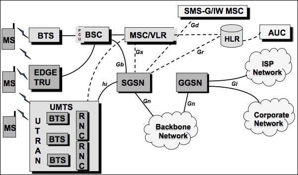
Cellular Concepts - GPRS Architecture
The following new GPRS network adds the following elements to an existing GSM network.
Packet Control Unit (PCU).
Serving GPRS Support Node (SGSN) − the MSC of the GPRS network.
Gateway GPRS Support Node (GGSN) − gateway to external networks.
Border Gateway (BG) − a gateway to other PLMN.
Intra-PLMN backbone − an IP based network inter-connecting all the GPRS elements.
General Packet Radio Service (GPRS)
GPRS introduces packet data transmission to the mobile subscriber.
GPRS is designed to work within the existing GSM infrastructure with additional packet switching nodes.
This packet mode technique uses multi-slot technology together with support for all coding schemes (CS-1 to CS-4) to increase the data rates up to 160 kbit/s.
The GPRS system uses the physical radio channels as defined for GSM. A physical channel used by GPRS is called a Packet Data Channel (PDCH).
The PDCHs can either be allocated for GPRS (dedicated PDCH) or used by GPRS only if no circuit-switched connection requires them (on-demand). The operator can define 0-8 dedicated PDCHs per cell. The operator can specify where he wants his PDCHs to be located.
The first dedicated PDCH in the cell is always a Master PDCH (MPDCH). The on-demand PDCHs can be pre-empted by incoming circuit switched calls in congestion situations in the cell.
| Coding Scheme | Speed(kbit/s) |
| CS-1 | 8.0 |
| CS-2 | 12.0 |
| CS-3 | 14.4 |
| CS-4 | 20.0 |
Serving GPRS Support Node (SGSN) Functions
The SGSN or Serving GPRS Support Node element of the GPRS network provides a number of takes focused on the IP elements of the overall system. It provides a variety of services to the mobiles −
- Packet routing and transfer
- Mobility management
- Authentication
- Attach/detach
- Logical link management
- Charging data
There is a location register within the SGSN and this stores the location information (e.g., current cell, current VLR). It also stores the user profiles (e.g., IMSI, packet addresses used) for all the GPRS users registered with the particular SGSN.
Gateway GPRS Support Node (GGSN) Functions
The GGSN, Gateway GPRS Support Node is one of the most important entities within the GSM EDGE network architecture.
The GGSN organizes the inter-working between the GPRS/EDGE network and external packet switched networks to which the mobiles may be connected. These may include both Internet and X.25 networks.
The GGSN can be considered to be a combination of a gateway, router and firewall as it hides the internal network to the outside. In operation, when the GGSN receives data addressed to a specific user, it checks if the user is active, then forwards the data. In the opposite direction, packet data from the mobile is routed to the right destination network by the GGSN.
Upgradation of Equipment from GSM to GPRS
Mobile Station (MS) − New Mobile Station is required to access GPRS services. These new terminals will be backward compatible with GSM for voice calls. Three types of handsets are available. Type-A: GPRS & Speech (simultaneously), Type-B: GPRS & Speech (Auto switch), Type-C: GPRS or Speech (manual switch).
BTS − A software upgrade is required in the existing base transceiver site.
BSC − Requires a software upgrade and the installation of new hardware called the packet control unit (PCU). PCU is responsible for handling the Medium Access Control (MAC) and Radio Link Control (RLC) layers of the radio interface and the BSSGP and Network Service layers of the Gb interface. There is one PCU per BSC. The Gb interface, carry GPRS/EGPRS traffic from the SGSN (Serving GPRS Support Node) to the PCU.
GPRS Support Nodes (GSNs) − The deployment of GPRS requires the installation of new core network elements called the serving GPRS support node (SGSN) and gateway GPRS support node (GGSN).
Databases (HLR, VLR, etc.) − All the databases involved in the network will require software upgrades to handle the new call models and functions introduced by GPRS.
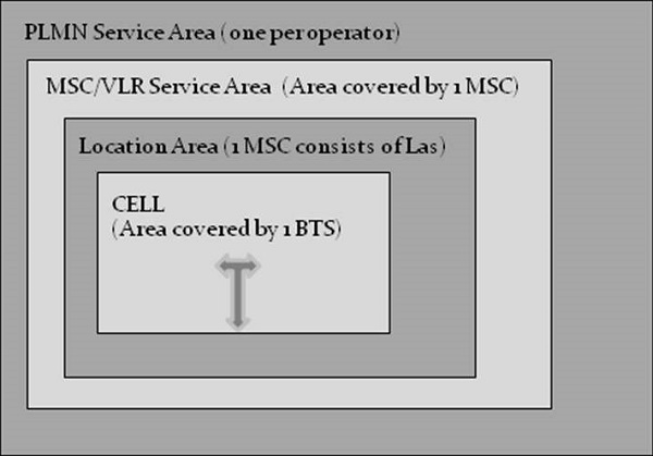
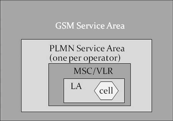
Location Information - GSM Service Area Hierarchy
Cell − Cell is the basic service area and one BTS covers one cell. Each cell is given a Cell Global Identity (CGI), a number that uniquely identifies the cell.
LA − A group of cells form a Location Area. This is the area that is paged when a subscriber gets an incoming call. Each Location Area is assigned a Location Area Identity (LAI). Each Location Area is served by one or more BSCs.
MSC/VLR Service Area − The area covered by one MSC is called the MSC/VLR service area.
PLMN − The area covered by one network operator is called PLMN. A PLMN can contain one or more MSCs.
GSM Service Area − The area in which a subscriber can access the network.
Cellular Concepts - Edge
Enhanced Data rates for Global Evolution (EDGE) introduces a new modulation technique, as well as protocol enhancements for transmitting packets over the radio.
The use of the new modulation and the protocol enhancements, result in dramatically increased throughput and capacity gains enabling 3G services in the existing GSM/GPRS networks. No changes are needed to the existing core network infrastructure to support EDGE. This emphasizes the fact that EDGE is only an “add-on” for BSS.
For EDGE, nine Modulation and Coding Schemes (MCS) are introduced (MCS1 to MCS9) and optimized for different radio environment. Four EDGE coding schemes are using GMSK and five are using 8 PSK Modulation.
Upgradation to EDGE
Mobile Station (MS) − MS should be EDGE enabled.
BTS − HW supplied is Edge enabled.
BSC − Definitions for EDGE timeslots needs to be done in BSC.
GPRS Support Nodes (GSNs) − Definitions for Edge need to be defined in GSNs.
Databases (HLR, VLR, etc.) − No definition is required.
Benefits of EDGE
- Short-term benefits − Capacity and performance,
- Easy implementation on a GSM/GPRS network,
- Cost effective,
- Increases the capacity and triples the data rate of GPRS,
- Enables new multimedia services,
- Long-term benefit − Harmonization with WCDMA.
What EDGE Would Mean to Subscribers
- Streaming applications
- Very high speed downloads
- Corporate intranet connections
- Quicker MMS
- Video phone
- Vertical corporate applications - Video conference, Remote presentations.
UMTS - A New Network
The Universal Mobile Telecommunications System (UMTS) is a third generation mobile cellular system for networks based on the GSM standard. Developed and maintained by the 3GPP (3rd Generation Partnership Project), UMTS is a component of the Standard International Union all IMT-2000 telecommunications and compares it with the standard set for CDMA2000 networks based on competition cdmaOne technology. UMTS uses wideband code division multiple access (W-CDMA) radio access technology to provide greater spectral efficiency and bandwidth mobile network operators.
Network Evolution
An Evolution that Makes Sense
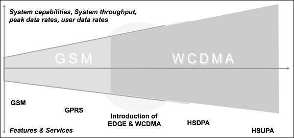
HSUPA − High Speed Uplink Packet Access
HSDPA − High speed downlink packet access
The main idea behind 3G is to prepare a universal infrastructure able to carry existing and also future services. The infrastructure should be so designed that technology changes and evolution can be adapted to the network without causing uncertainties to the existing services using the existing network structure.
UMTS - WCDMA Technology
The first Multiple Access Third Generation Partnership Project (3GPP) Wideband Code Division networks (WCDMA) were launched in 2002. At the end of 2005, there were 100 WCDMA networks open and a total of more than 150 operators with licenses for frequencies WCDMA operation. Currently, WCDMA networks are deployed in UMTS band of around 2 GHz in Europe and Asia, including Japan and America Korea. WCDMA is deployed in the 850 and 1900 of the existing frequency allocations and the new 3G band 1700/2100 should be available in the near future. 3GPP has defined WCDMA operation for several additional bands, which are expected to be commissioned in the coming years.
As WCDMA mobile penetration increases, it allows WCDMA networks to carry a greater share of voice and data traffic. WCDMA technology provides some advantages for the operator in that it allows the data, but also improves the voice of base. Voice capacity offered is very high due to interference control mechanisms, including frequency reuse of 1, fast power control, and soft handover.
WCDMA can offer a lot more voice minutes to customers. Meanwhile WCDMA can also improve broadband voice service with AMR codec, which clearly provides better voice quality than fixed telephone landline. In short, WCDMA can offer more voice minutes with better quality.
In addition to the high spectral efficiency, third-generation (3G) WCDMA provides even more dramatic change in capacity of the base station and the efficiency of the equipment. The high level of integration in the WCDMA is achieved due to the broadband carrier: a large number of users supported by the carrier, and less radio frequency (RF) carriers are required to provide the same capacity.
With less RF parts and more digital baseband processing, WCDMA can take advantage of the rapid evolution of digital signal processing capability. The level of integration of the high base station enables efficient building high capacity sites since the complexity of RF combiners, additional antennas or power cables can be avoided. WCDMA operators are able to provide useful data services, including navigation, person to person video calls, sports and video and new mobile TV clips.
WCDMA enables simultaneous voice and data which allows, for example, browsing or email when voice conferencing or video sharing in real time during voice calls.
The operators also offer mobile connectivity to the Internet and corporate intranet with maximum bit rate of 384 kbps downlink and both uplink. The first terminals and networks have been limited to 64 to 128 kbps uplink while the latter products provide 384 kbps uplink.
WCDMA-3G
3G wireless service has been designed to provide high data speeds, always-on data access, and greater voice capacity. Listed below are a few notable points −
The high data speeds, measured in Mbps, enable full motion video, high-speed internet access and video-conferencing.
3G technology standards include UMTS, based on WCDMA technology (quite often the two terms are used interchangeably) and CDMA2000, which is the outgrowth of the earlier CDMA 2G technology.
UMTS standard is generally preferred by countries that use GSM network. CDMA2000 has various types, including 1xRTT, 1xEV-DO and 1xEV-DV. The data rates they offer range from 144 kbps to more than 2 mbps.
Sub-systems of 3G Network
A GSM system is basically designed as a combination of three major subsystems −
Network Subsystem (NSS) − MSC/VLR, HLR, AuC, SMSC, EIR, MGW. Common for both 2G & 3G Network.
UTRAN − RNC & RBS.
Operation and maintenance Support Subsystem (OSS).
There are three dominant interfaces, namely,
IuCS − Between RNC and MSC for speech & Circuit data;
IuPS − Between RNC & SGSN for packet data;
Uu interface − Between the RNC and MS.
UMTS - HSPA Standardization
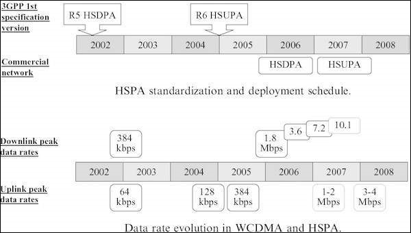
Let's look at the standardization and deployment schedule of HSPA in brief −
High-speed downlink packet access (HSDPA) was standardized as part of 3GPP Release 5 with the first specification version in March 2002.
High-speed uplink packet access (HSUPA) was part of 3GPP Release 6 with the first specification version in December 2004.
HSDPA and HSUPA together are called High-Speed Packet Access’ (HSPA).
The first commercial HSDPA networks were available at the end of 2005 and the commercial HSUPA networks were available on 2007.
The HSDPA peak data rate available in the terminals is initially 1.8Mbps and will increase to 3.6 and 7.2 Mbps during 2006 and 2007, and later on 10Mbps and beyond 10Mbps.
The HSUPA peak data rate in the initial phase was 1–2 Mbps and the second phase was 3–4Mbps.
HSPA is deployed over the WCDMA network on the same carrier or - for high capacity and high speed solution - using another carrier, see figure above. In both cases, WCDMA and HSPA can share all the network elements in the core network and the radio network comprising base stations, radio network controller (RNC), Serving GPRS Support Node (SGSN) and the Gateway GPRS Support Node (GGSN). WCDMA and HSPA also share the site base station antennas and antenna cables.
The upgrade WCDMA HSPA requires new software and potentially new equipment in the base station and RNC to support the rate and higher data capacity. Because of the shared infrastructure between WCDMA and HSPA, the cost of the upgrade WCDMA HSPA is very low compared to the construction of a new stand-alone data network.
UMTS - Objectives
Of many, below mentioned are few objectives of UMTS −
UMTS - Radio Interface and Radio Network Aspects
After the introduction of UMTS the amount of wide area data transmission by mobile users had picked up. But for the local wireless transmissions such as WLAN and DSL, technology has increased at a much higher rate. Hence, it was important to consider the data transmission rates equal to the category of fixed line broadband, when WIMAX has already set high targets for transmission rates. It was clear that the new 3GPP radio technology Evolved UTRA (E-UTRA, synonymous with the LTE radio interface) had to become strongly competitive in all respect and for that following target transmission rates were defined −
- Downlink: 100 Mb/s
- Uplink: 50 Mb/s
Above numbers are only valid for a reference configuration of two antennas for reception and one transmit antenna in the terminal, and within a 20 MHz spectrum allocation.
UMTS – All IP Vision
A very general principle was set forth for the Evolved 3GPP system. It should “all IP”, means that the IP connectivity is the basic service which is provided to the users. All other layer services like voice, video, messaging, etc. are built on that.
Looking at the protocol stacks for interfaces between the network nodes, it is clear that simple model of IP is not applicable to a mobile network. There are virtual layers in between, which is not applicable to a mobile network. There are virtual layer in between, in the form of “tunnels”, providing the three aspects - mobility, security, and quality of service. Resulting, IP based protocols appear both on the transport layer (between network nodes) and on higher layers.
UMTS – Requirements of the New Architecture
There is a new architecture that covers good scalability, separately for user plane and control plane. There is a need for different types of terminal mobility support that are: fixed, nomadic, and mobile terminals.
The minimum transmission and signaling overhead especially in air, in an idle mode of the dual mode UE signaling should be minimized, in the radio channel multicast capability. It is required to be reused or extended, as roaming and network sharing restrictions, compatible with traditional principles established roaming concept, quite naturally, the maximum transmission delay required is equivalent to the fixed network, specifically less than 5 milliseconds, set to control plane is less than 200 milliseconds delay target.
Looking at the evolution of the 3GPP system in full, it may not seem less complex than traditional 3GPP system, but this is due to the huge increase in functionality. Another strong desire is to arrive at a flat structure, reducing CAPEX/OPEX for operators in the 3GPP architecture carriers.
Powerful control functions should also be maintained with the new 3GPP systems, both real-time seamless operation (for example, VoIP) and non-real-time applications and services. The system should perform well for VoIP services in both the scenarios. Special attention is also paid to the seamless continuity with legacy systems (3GPP and 3GPP2), supports the visited network traffic local breakout of voice communications.
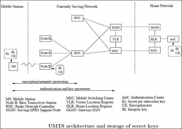
UMTS – Security and Privacy
Visitor Location Register (VLR) and SNB are used to keep track of all the mobile stations that are currently connected to the network. Each subscriber can be identified by its International Mobile Subscriber Identity (IMSI). To protect against profiling attacks, the permanent identifier is sent over the air interface as infrequently as possible. Instead, local identities Temporary Mobile Subscriber force (TMSI) is used to identify a subscriber whenever possible. Each UMTS subscriber has a dedicated home network with which it shares a secret key Ki long term.
The Home Location Register (HLR) keeps track of the current location of all the home network subscribers. Mutual authentication between a mobile station and a visited network is carried out with the support of the current GSN (SGSN) and the MSC / VLR, respectively. UMTS supports encryption of the radio interface and the integrity protection of signaling messages.
UMTS - Authentication
UMTS is designed to interoperate with GSM networks. To protect GSM networks against man-in-middle attacks, 3GPP is considering to add a structure RAND authentication challenge.
UMTS Subscriber to UMTS Network
Both the network and the mobile station supports all the security mechanisms of UMTS. Authentication and Key agreement is as follows −
The mobile station and the base station to establish a radio resource control connection (RRC connection). During the establishment of the connection the mobile station sends its security capabilities to the base station. Security features include UMTS integrity and encryption algorithms supported and possibly GSM encryption capabilities as well.
The mobile station sends its temporary identity TMSI current on the network.
If the network cannot solve the TMSI, he asks the mobile station to send its permanent identity and the mobile stations responding to the request with the IMSI.
The visited network requests authentication of the home network of the mobile station data.
The home network returns a random challenge RAND, the corresponding authentication token AUTN, authentication
Response XRES, integrity key IK and the encryption key CK.
The visited network sends RAND authentication challenge and authentication token AUTN to the mobile Station.
The mobile station checks AUTN and calculates the authentication response. If AUTN is corrected.
Mobile station ignores the message.
The mobile station sends its authentication response RES to the visited network.
Visiting the network checks if RES = XRES and decide which security algorithms radio subsystem is allowed to use.
The visited network sends algorithms admitted to the radio subsystem.
The radio access network decides permit (s) algorithms to use.
The radio access network informs the mobile station of their choice in the security mode command message.
The message also includes the network security features received from the mobile station in step 1.
This message is integrity protected with the integrity key IK.
The mobile station confirms the protection of the integrity and verify the accuracy of the safety functions.
UMTS Subscriber to GSM Base Station
The mobile unit (subscriber UMTS) supports both USIM and SIM application. The base station system uses GSM while the VLR / MSC technology components are respectively the UMTS SGSN. The mobile station and the core network both support all security mechanisms of UMTS. However, the base station system GSM (BSS) does not support the protection of the integrity and uses the GSM encryption algorithms. The first eight steps of the authentication protocol are performed as in the classical case. GSM BSS simply forwards the UMTS authentication traffic.
The MSC / SGSN decides which GSM encryption algorithms are allowed and calculates the key GSM Kc UMTS keys IK, CK.
The MSC / SGSN advises the GSM BSS authorized algorithms and transmits the GSM cipher key Kc.
GSM BSS decide which encryption algorithms allowed to use based encryption capabilities of the mobile station.
GSM BSS sends the GSM cipher mode command to the station.
UMTS - Success and Limitations
The success story of GSM (2G) is exceptional. To facilitate data communication, some extensions were made in existing GSM, but the success was limited. GPRS was introduced for mobile users for packet data, basic data rate went up to 172 Kb/s in theory, but hardly allocated the maximum 8 logical channels for a user. GPRS has the concept of a 2 stage access to IP connectivity.
First step is to connect to and register with the network. For this the transmission of user data requires the establishment of PDP (Packet Data Protocol) environment. At this point only the IP address is assigned. GPRS is also known as 2.5G network.
For both GSM/CS (Circuit Switching) and GPRS/PS (Packet Switching), continuous efforts for optimizations were made on the basis of higher modulation efficiency under EDGE (Enhanced Data Rates for GSM Evolution), but nothing was changed fundamentally.
The next 3G generation of mobile networks (UMTS) built on a new radio technology known as WCDMS (Wideband CDMA) and it ensured two things −
- More bandwidth due to new radio spectrum;
- Higher peak data rates for the end user.
UMTS network architecture was designed keeping both CS and PS in parallel. Later on, a completely different service layer was created in form of the Internet and Multimedia Subsystem (IMS). UMTS was latter on improved for higher data rates by HSPA and HSPA+. This was divided into downlink/HSDPA and uplink/HSUPA. 3GPP Rel 5 has standardized for HSDPA and Rel 6 has standardized for HSUPA. HSPA+ comes under Rel. 7 standard of 3GPP.
Continuous improvement was achieved already within the legacy PS technology by Direct Tunnel approach. However, it was clear that more changes in architecture are required to achieve this goal. Another aspect of improvement in the legacy technology can be identified with supernatural efficiency, the effective number of bits deliverable per radio frequency unit and time unit. Even though new radio spectrum has been made available for mobile communication, the pressure for cost reduction and competitiveness required further gain.
UMTS - 3GPP
3GPP is the standardization group for mobile networks and is in existence since 1998. 3GPP specification come in bundles called “Release”.
3rd Generation Partnership Project (3GPP)
3GPP releases are from Release 99 to Release 7.
| Release | Published | Key Architectural Features |
|---|---|---|
| Release 99 | March 2000 | UTRAN, USIM |
| Release 4 | March 2001 | MSC Split into MSC server and Media Gateway |
| Release 5 | March 2002 | IMS, HSPDA, IP based UTRAN |
| Release 6 | March 2005 | I-WLAN, HSUPA, MBMS, IMS |
| Release 7 | Dec 2007 | Unified PCC, Direct Tunnel, MIMO, HSPA+, IMS, VCC |
The network entities in brief are −
| UE | User Equipment: the mobile terminal |
| BTS | Base Transceiver Station: the 2G/2,5G radio base station |
| BSC | Base Station Controller: a controlling node in the 2G radio network |
| NodeB | 3G radio base station |
| RNC network | Radio NW controller: controlling and concentrating node in the 3G radio |
| (G)MSC Nodes | (Gateway) Mobile Switching Center: circuit switched core network |
| S/GGSN Nodes | Serving/Gateway GPRS Support Node: packet switched core network |
| HLR/HSS base | Home Location Register / Home Subscription Server: central data |
| PCRF | Policy and Charging Rules Function: a control node for policy management and charging |
3rd Generation Partnership Project 2 (3GPP2)
3GPP2 is the corresponding part of 3GPP market. 3GPP2 standards body has also developed a large set of specifications describing own mobile network technology, the current generation being labeled as CDMA2000 ©. 3GPP2 is 3GPP concepts and solutions, but is chosen selectively different. Regarding LTE, there has been a growing interest of 3GPP2 operators in recent years to allow between flexible and efficient. The inheritance 3GPP2 technology includes a component called 1xRTT CS and PS component (EVDO vs eHRPD). 3GPP2 consider their (eHRPD) high-speed packet data network as equivalent to 3GPP old system, the right to transfer procedures optimized specially designed.
Architecture of the 3GPP System
The overall architecture of the 3GPP, evolved system as well as the core and access networks already existing 3GPP defined are called "legacy 3GPP system".
The access networks which are not defined by the 3GPP, but may be used in conjunction with the evolved 3GPP system are called "non-3GPP access networks".
The area of service must be understood as the multitude of IP services, so in general they are represented and implemented by packet data networks (PDN). IP service can simply offer a raw IP connectivity (i.e. allowing an internet connection), providing a connection to a corporate network, or an advanced IP-based control functionality such as telephony and instant messaging via IMS.
It is called "Evolved UTRAN" (EUTRAN). GERAN and UTRAN are the existing radio access networks and are connected to the legacy PS domain.
Evolved Packet Core (EPC) in addition to the basic functions to manage packet routing and forwarding (for the transport of user data) contains all the features necessary to control especially for mobility, session handling, safety and load.
For interworking with legacy CS domain, the CS core network should be considered as well and interfaced with the backend IMS. The dotted arrow indicates an optional interconnection between legacy CS core networks and the new network Evolved Packet Core, the decline in profit to the CS domain for voice services, if necessary.
UMTS - Radio Access Network
The more general term "Evolved Radio Access Network" (eRAN), can also be used as part of signaling protocols, as the term "access stratum" (AS) can be used. The comparison reveals that E-UTRAN consists of one type of nodes, namely Evolved Node B (eNodeB), and the variety of interconnections is reduced to a minimum. eNodeB is a radio base station and transmits/receives via its antenna in an area (cell), limited by physical factors (signal strength, interference conditions, and conditions of radio wave propagation). It has logical interfaces X2 with neighboring eNodeB and the EPC via S1. Both have a control part (that is, say for signaling) and a user plane part (for payload data).
Point to the EU reference (which includes radio link interface and a mobile network protocol stack bound) is called "LTE-U u" to indicate that it differs from the legacy counterpart EU X2 connectivity neighboring eNodeBs. They may be considered for most of the E-UTRAN and is used in most cases of handovers between radio cells.
As the UE moves, long handover preparation is done via signaling, through X2 between the two data eNodeBs and affected users can be transmitted between them for a short period of time. Only in special cases, it may happen that X2 is not configured for eNodeB between two neighbors. In this case transfers are always supported, but the preparation of transfer and the data transmission is then made via the EPC. Accordingly, higher latency and less "homogeneity" must therefore be provided.
In more detail, the functions performed by the eNodeB are −
Radio Resource Management: Radio Bearer Control, Radio Admission Control, Connection Control Mobility, dynamic allocation of resources (i.e. scheduling) to UES as uplink and downlink.
Header compression of IP and encryption of user data stream.
Forwarding the data packets of user plane to the EPC (especially, toward the GW node service).
Transport level packet marking in the uplink, for example, DiffServ code point setting, based on the QoS class index (QCI) of the EPS bearer associated. Planning and delivery of paging messages (on request of MS).
Planning and transmission of broadcast information (origin of the MME or O & M).
Measurement configuration delivering and reporting on the extent of mobility and programming.
UMTS - Evolved Packet Core (EPC) Network
By the early architectural work for the system evolved 3GPP, two views on the implementation of mobility with the user plane and control plane protocols were presented.
The first was promoted as the good performance of the GPRS Tunneling Protocol (GTP), while the other pushed for the new (and the so-called "base" of the IETF) protocols.
Both had good arguments on their side −
GTP evolution − This protocol has proven its usefulness and capabilities to operators, and was very successful in the large scale operations. It was designed exactly to the needs of the mobile networks PS.
IETF based protocols − IETF is the de facto standards body for the internet. Their mobility protocols have evolved from focusing on mobile IP-based network client to "Proxy Mobile IP (MIP)." PMIP was standardized in 3GPP Evolved parallel system. (But Mobile IP client base is used in EPS in conjunction with non-3GPP access support.)
EPC for 3GPP access in non-roaming
The functions provided by the reference points and the protocols employed are −
LTE-Uu
LTE-Uu is the point of reference for radio interface between EU and eNodeB, encompasses control plane and user plane. The top layer of the control plan is called "Radio Resource Control" (RRC). It is stacked on "Packet Data Convergence Protocol" (PDCP), Radio Link Control and MAC layers.
S1-U
SI-U is the point for user plane traffic between eNodeB and serve GW reference. The main activity via this benchmark is to transfer IP packets encapsulated users arising from traffic or tunnel shape. Encapsulation is needed to realize the virtual IP link between eNodeB and GW service, even during the movement of EU, and thus enable mobility. The protocol used is based on GTP-U.
S1-MME
S1-MME is the point for the control plane between eNodeB and MME reference. All control activities are carried out on it, for example, signaling for attachment, detachment, and the establishment of the support of the change, safety procedures, etc. Note that some of this traffic is transparent to the E-UTRAN and is exchanged directly between EU and MS, it is a part called "non-access stratum" (NAS) signaling.
S5
S5 is the benchmark that includes the control and user plane between GW and PDN GW Service and applies only if both nodes reside in the HPLMN; the corresponding reference point when serving GW is VPLMN is called S8. As explained above, two protocol variants are possible here, an enhanced GPRS Tunneling Protocol (GTP) and Proxy Mobile IP (PMIP).
S6a
S6a is the reference point for the exchange of information relating to subscriptions equipment (download and purging). It corresponds to Gr and D reference point in the existing system, and is based on the DIAMETER protocol.
SGi
This is the point of exit for DPR, and corresponds to the Gi reference point GPRS and Wi in I-WLAN. IETF protocols are based here for the user plane (i.e. IPv4 and IPv6 packet forwarding) protocols and control plane as DHCP and radius/diameter for configuring IP address/external network protocol are used.
S10
S10 is a reference point for the MME relocation purposes. It is a pure control plane interface and advanced GTP-C protocol is used for this purpose.
S11
S11 is a reference point for the existing control plane between MME and GW service. It employs the advanced GTP-C (GTP-C v2) protocol. The holder(s) of data between eNodeB and serve GW are controlled by the concatenation S1-S11 and MME.
S13
S13 is the reference point for Equipment Identity Register (EIR) and MME, and it is used for identity control (e.g. based on IMEI, if blacklisted). It uses the diameter protocol SCTP.
Gx
Gx is the reference point of the QoS policy filtering policy and control the load between PCRF and PDN GW. It is used to provide filters and pricing rules. The protocol used is the DIAMETER.
Gxc
Gxc is the reference point that exists in over Gx but is located between GW and PCRF and serves only if PMIP is used on S5 or S8.
Rx
Rx is defined as an application function (AF), located in NDS and PCRF for the exchange of policy and billing information; it uses the DIAMETER protocol.
EPC for 3GPP Access in Roaming
In roaming this case the user plane either −
Extends back to the HPLMN (via an interconnection network), which means that all EU user traffic is routed through a PDN GW in the HPLMN, where the DPRs are connected; or
For the sake of a more optimal way of traffic, it leaves a PDN GW in the VPLMN to a local PDN.
The first is called "home routed traffic" and the second is called "local breakout". (Note that the second term is also used in the discussion of traffic optimization for home NBs/eNodeB, but with a different meaning because in the concept of roaming 3GPP, the control plan always involves the HPLMN).
Interworking between EPC and Legacy
From the beginning, it was clear that the 3GPP Evolved system will interoperate seamlessly with existing 2G and 3G systems, 3GPP PS widely deployed or, more precisely, with GERAN and UTRAN GPRS base (For aspects of interworking with the old CS system for the treatment of optimized voice).
The question of the basic architectural design to 2G/3G in EPS is the location of the GGSN map. Two versions are available, and both are supported −
The GW used − It is the normal case where serving the GW ends the user plane (as seen in the existing GPRS network).
The control plan is completed in the MME, according to the distribution of users and control plane in EPC. S3 and S4 reference points are introduced, and they are based on GTP-U and GTP-C, correspondingly. S5/S8 is chained to the PDN GW. The advantage is that interoperability is smooth and optimized. The downside is that for this kind of interoperability SGSN must be upgraded to Rel. 8 (due to the necessary support new features on S3 and S4).
The PDN GW − In this case the unchanged benchmark inheritance Gn (when roaming, it would Gp) is reused between SGSN and PDN GW, for both control and user plane. The advantage of this use is that SGSN can be pre-Rel. 8. Furthermore, it carries a certain restriction on IP versions, transfer and S5 / S8 protocol.
Interworking with Legacy 3GPP CS System
During the 3GPP Evolved design phase, it became clear that the legacy CS system, with its most important service "voice" communication, could not be ignored by the new system. The operators were simply too related investments in the field, and so very efficient interworking was requested.
Two solutions have been developed −
Single Radio Voice Call Continuity (SRVCC) for transferring voice calls from LTE (with voice over IMS) to the legacy system.
CS fallback − Enabling a temporary move to the legacy CS before a CS incoming or outgoing activity is performed.
Single Radio Voice Call Continuity (SRVCC)
In this solution chosen by 3GPP for SRVCC with GERAN/UTRAN, a specially reinforced MSC is connected via a new interface control plane for MME.
Note that the MSC serving the EU can be different than supporting the Sv interface. In the IMS, an application server (AS) for SRVCC is necessary. Sv is based on GTPv2 and helps prepare resources in the target system (access and core network and the interconnection between CS and IMS domain), while being connected to access the source.
Similarly, with SRVCC CDMA 1xRTT requires interworking 1xRTT Server (IWS), which supports the interface and signal relay from / to 1xRTT MSC serving the UE S102 with the same purpose. S102 is a tunnel interface and transmits 1xRTT signaling messages; between MME and UE these are encapsulated.
CS Fallback
Serving GW and PDN GW are not separated (S5/S8 is not exposed) and the VLR is integrated with the MSC server. A new SG interface is introduced between the MSC Server/VLR and MME, allowing combined and coordinated procedures. The concept consists of −
Signal relay to end the CS request (incoming calls, handling network triggered additional service or SMS Legacy) from the MSC Server for MS on SG and vice versa;
The combined operating procedures between the PS domain and the CS domain.
Interworking with Non-3GPP Access
Interworking with different system of 3GPP access networks (called non-3GPP/access) was an important target for SAE; this should be done under the EPC umbrella. This interoperability can be achieved at different levels (and in fact, this was done on the layer 4 with VCC/SRVCC). But for the generic type of interworking, it seemed necessary to rely on generic mechanisms, so the IP level seemed most appropriate.
In general, complete systems for mobile and fixed networks have an architecture similar to that described above. For the evolved 3GPP system there is normally an access network and a core network. In the interworking architecture scheduled evolved 3GPP system, other access technologies systems connect to the EPC.
In general, complete mobile network system and fixed network systems have a similar architecture as described outlined in Evolved 3GPP system and normally consist of an access network and a core network.
It was also decided to allow two different types of interoperability, based on the property of the access systems. For networks with non-3GPP access confidence, it is assumed that secure communication between them and the EPC is implemented and also robust data protection is sufficiently guaranteed.
UMTS - GPRS Tunneling Protocol
The generation of GPRS Tunneling Protocol (GTP) was virtually impossible, but is also not desirable to give it for the new system, but, on the other hand, it is quite understandable that the improvements are also needed in order to be able to interact with the world of legacy PS smoothly and support functions needed for the newest system.
GPRS Tunneling Protocol (GTP)
GTP protocol is designed for tunneling and encapsulation of data units and control messages in GPRS. Since its design in the late 1990s, it was put to deploy on a large scale, and solid experience has been gathered.
GTP for Evolved 3GPP system is available in two variants, control and user plane. GTP-C manages the control plane signaling, and it is necessary in addition to the data transfer protocol on the purity of the user, GTP-U; it is called user plane. Current versions, suitable for EPS are GTPv1 US and GTPv2-C.
The peculiarity of GTP is that it supports the separation of traffic within its primary GTP tunnel holder, or in other words, the ability to group them together and treat carriers. The ends of GTP tunnels are identified by TEIDs (Tunnel Endpoint identifiers); they are assigned to the local level for the uplink and downlink by peer entities and reported transversely between them. TEIDs are used on different granularity by specific example PDN connection on S5 and S8 and EU on S3 / S4 / S10 / S11 interfaces.
Control Plane of GPRS Tunneling Protocol
GTPv2-C is used on the EPC signaling interfaces (including SGSNs of at least Rel. 8). For example −
- S3 (between SGSN and MME),
- S4 (between SGSN and Serving GW),
- S5 and S8 (between Serving GW and PDN GW),
- S10 (between two MMEs), and
- S11 (between MME and Serving GW).
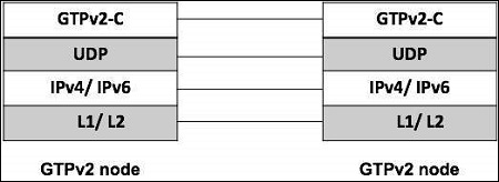
Corresponding to this, a typical GTPv2-C protocol data unit like shown in the figure above, the specific part GTP is preceded by IP and UDP headers, it consists of a header GTPv2-C and part containing information GTPv2-C variable in number, length and format, depending on the type of the message. As the echo and the notification of a protocol version is not supported, TEID information is not present. The version is obviously firmly set at 2 in this version of the protocol.
GTP had a complex legacy extension header mechanism; it is not used in most GTPv2-C. The message type is defined in the second byte (so the maximum of 256 messages can be defined for future extensions). Below table provides an overview of messages currently defined GTPv2-C. The length of the message is coded in bytes 3 and 4 (measured in bytes and not containing the first four bytes themselves).
TEID is the ID of the tunnel end point, a single value on the opposite/receiving side; it allows multiplexing and de-multiplexing tunnels at one end in the very frequent cases over a GTP tunnel must be distinguished.
| Message Type | Message | Additional Explanation |
|---|---|---|
| 0 | Reserved | Shall never be used (intentionally excluded from protocol, to enforce explicit setting) |
| 1/2 | Echo Request/ Response | Used to probe if a GTP version supported by the sending node. |
| 3 | Version Not Supported Indication | Contains the latest GTP version supported the sending node. |
| 4/5 | Direct Transfer Request/ Response | Used for tunneling signaling message on S101 interface for optimized handover, between HRPD access not and MME |
| 6/7 | Notification Request/ Response | Used for tunneling notification on S101 between HRPD access node and MME |
| 25/26 | SRVCC PS to CS request | Used to trigger and confirm SRVCC initiation between SGSN/MME and MSC server |
| 27/28 | SRVCC PS to CS complete Notification | Used to indicated and confirm completion of SRVCC between MSC server and SGSN/ MME |
| 32/33 | Create Session Request | Used to establish connectivity between two nodes |
| 34/35 | Modify Bearer Request | Used to modify properties of a single or of multiple bearer, include bearer context information |
| 36/37 | Delete Session Request | Tears down GTP control session |
| 38/39 | Change Notification request | Used for reporting location information |
| 66/67 | Delete bearer command/ failure indication | Instruct nodes to delete bearer and confirm back |
| 68/69 | Bearer resource command/ failure indication | Used to allocate or modify resources |
| 73 | Stop paging indication | Sent from SGW to the MME or SGSN |
| 95/96 | Create bearer request/ response | Instruct nodes to install bearers and confirms back |
| 97/98 | Update bearer request | Used to inform the control plane nodes from the user plane about bearer changes |
Enhanced GTPv1-U
Only a small but effective improvement was applied to GTP-U, and for that it was not considered necessary to strengthen the number of protocol version. Thus, we still expect GTPv1-U, but at least it’s most recent Rel. 8.
The protocol stack is essentially the same as for GTPv2-C with only the name of the layers and the protocols substituted accordingly. The extension header mechanism is kept in place; it allows inserting two elements if necessary.
UDP source port of the triggering message (two octets);
PDCP PDU number − related to the characteristic transfer without loss; in this case, data packets need to be numbered in the EPC (two octets).
The improvement is the ability to transmit an "end market" in the user plane. It is used in the inter-eNodeB handover procedure and gives the indication that the pathway is activated immediately after the data packet, for example, the feature is not necessary to pre-Rel.8 because GTP-U did not end in the radio access node (i.e. not in the BS or NodeB) only a few messages exist. GTPv1-U, and they are listed in the table above.
It is clear that, in fact a very limited kind of signaling is possible via GTPv1-U (echo mechanisms and end labeling). The only message that the transfer of real user data is of type 255, the so-called G-PDU message; the only piece of information it carries, after the header is the original data packet from a user or external PDN equipment.
Not all instances of GTP-U tunnels are listed in the reference architecture (which aimed to capture the associations were no longer living between network nodes); temporary tunnels are possible −
Between two Serving GWs, applicable for the transfer based on S1, in the case that the service is moved GW;
Between two SGSNs, corresponds to the previous case, but in the legacy PS network;
Between two RNCs, applicable for the relocation of the RNC in the 3G PS network (no relation to the EPC, it is mentioned here just for completeness).
UMTS - Proxy Mobile IPv6 Protocol
It is a mobility management protocol standardized by Internet Engineering Task Force (IETF) which works on developing internet protocol standards.
Dual Stack Capability
Dual stack capability for PMIPv6 has two targets −
To support IPv4 home addresses
To allow IPv4 only transport across the access network; in this case the MAG may use also an IPv4 private address, and a NAT may be deployed along the path towards the LMA.
These two features can be used independently. To solve these requirements, the following extensions made −
In the Binding Cache of LMA −
IPv4 address assigned to the mobile node and now registered with the mobile access gateway (including corresponding subnet mask). It comes either from static configuration/profile or is dynamically allocated by LMA.
IPv4 default-router address assigned to the mobile node.
In the Binding Update list of MAG −
IPv4 home address assigned to the mobile attached interface.
IPv4 default router of the mobile node. The LMA and MAG should implement IPv6, and they also need an IPv4 address. MAG is the IPv4 Default Router for the UE on its access link.
PMIPv6 Signaling
Table below provides an overview of PMIPv6 signaling messages (basic PMIPv6 and specified improvements in IETF for connecting dismissal and way of management). Signaling PMIPv6 base is made with "Binding Update" (BU) MAG to LMA, and a corresponding "Update acknowledgment Binding" (BUA) messages back to MAG is used for registering, refreshing and binding deletion. IP address information (IPv4 or IPv6 address prefix) is usually requested by the LMA and MAG assigned by the initial enrollment.
| PMIPv6 Signaling Message | Direction | Description | |
|---|---|---|---|
| Binding Update | PBU | MAG → LMA | Requests creations, extension and deletion of a mobility binding. It is also used to request a new IPv4 address. |
| Binding Update Acknowledgement | PBA | LMA → MAG | Acknowledges the requests for creation, extension and deletion of a mobility binding. It is also used to allocate and IPv4 address. |
| Binding Revocation Indication | BRI | LAM → MAG | Notification that a binding is revoked and thus will be deleted by LAM, allows also bulk revocations. |
| Binding Revocation Acknowledgement | BRA | MAG → LMA | Acknowledges a binding revocation. |
| Heartbeat | HB |
MAG → LMA LMA → MAG |
Periodic signaling message, used for detecting failure. |
3GPP Specific Information Elements Added to PMIPv6
PMIPv6 is designed for a very general use; 3GPP has some special requirements arising from the need to make it compatible as possible with capacities of GTP.
| Vendor Specific Information | Direction | Explanation |
|---|---|---|
| Protocol Configuration Options | MAG → LMA LMA → MAG |
Mirrored from GTP, used to transfer frequently needed, protocol related data between UE and network. |
| Specific 3GPP related error code | LMA → MAG | It can indicate that no access is given to an APN. |
| Connection Set Identifier (CSI) |
LMA → MAG MAG → LMA |
Contains one or more CSIs. It is generated for each new PDN connection and used in case of partial node failure to identify the PDN. |
| PDN type indication | LMA → MAG | Used to indicate the decision of the PDN GW. |
| PDN GW IP address | MAG → LMA | Used in case of chaining on S2a/S2b to transfer to the intermediate LMA. |
| DHCPv4 address allocation indication | LMA → MAG | Indicates that IP at allocation through DHCPv4 is to be used by the UE. |
UMTS - Extensible Authentication Protocol
It is a generic framework developed by the IETF (RFC 3748). The basic signaling mechanism supports different authentication methods on top.
The EAP specific use for interworking with a 3GPP system is defined by the EAP-AKA method EAP-AKA is already used in I-WLAN.
The principal steps for EAP authentication are given below −
EAP authenticator sends an authentication request to the target device/EU (L2); it receives the response from the target device/EU and transmits it to the AAA infrastructure.
AAA server performs the EAP method, resulting in a challenge to the target device, which is sent by the authenticator.
The target device must meet the challenge; the answer is relayed to the AAA server via the authenticator.
AAA server compares the response to challenge with that expected and decides to successful authentication. An indication of success or failure is returned to the target device.
Optionally, the notifications can be used to transfer additional information; this is used for the IP mobility mode selection indication. During the design there was a major decision to separate areas of the safety of non-3GPP access networks in the field of security 3GPP, and also to the other domain.
The practical consequence is that the identifier of non 3GPP access network enters the security algorithm, which requires the specification of a variant of EAP-AKA, EAP-AKA (premium).
UMTS - IKEv2 & MOBIKE
Internet Key Exchange is a sophisticated version 2 defined by the IETF in RFC 4306. It allows creating and maintaining security associations and IPSec tunnels between two nodes and exchanging some configuration data; they are transferred to the so-called payload configuration dialogues in the message.
Comprehensive IKEv2 session consists of multiple dialogues, structured phases. The flow of messages and typical base is given in the figure below, and a description of how it is applied in the context of signaling between EU and ePDG −
| IKEv2Phase | Comments |
|---|---|
| Initial Exchange |
Notifies payload as MOBIKE support indication. IP address to be requested/ delivered in configuration payload. Home agent address to be requested/ provided in configuration payload. |
| Auth Exchange | |
| Create child SA | For creating protected tunnel for DSM IPv6 signaling |
| x. Information Exchange | At any point after AUTH. |
In the Evolved 3GPP system IKEv2 is used for −
- IP address information: either IPv4 address or IPv6 prefix.
- IP mobility mode selection information.
- IP address information: IPv6 prefix.
- DNS server address.
Diameter
The diameter is a generic AAA protocol, with additional functions for network access, mobility and QoS handling. Although it is in principle, of a general nature peer-to-peer, it is used in the 3GPP architecture in the client-server mode. It has a built-in extensibility and so perfectly supports message structures on the interfaces with the need for some flexibility. In addition, it supports multiple server configurations with failure and failover handling. Functionally, it has similarities with its predecessor radius but differs profoundly on the level of message and parameters. DIAMETER offers ability to detect a dead peer by pairs of heartbeat messages. It can be run over SCTP or TCP and uses the 3868 port.
The DIAMETER protocol is used extensively in the EPC −
S6a for subscription download and update between MME and HSS.
S6d (between an upgraded SGSN and HSS), which is the counterpart of S6a for the legacy world with interworking capability with the new system.
S13 for equipment checking between MME and EIR.
SWa for authentication between untrusted non-3GPP access and AAA server.
STa for authentication between trusted non-3GPP access and AAA server and authorization.
SWd for forwarding between an AAA proxy and a AAA server (forwarding between VPLMN and HPLMN).
S6b for authorization of APN and mobility between PDN GW and AAA server.
SWm for authentication and authorization between ePDG and AAA server.
SWx for exchange of authentication vector and registration information between AAA server and HSS.
Gx for IP-CAN session handling and GW-Control Session handling between PDN GW and PCRF.
UMTS - SCTP
Stream Control Transmission Protocol (SCTP) is a reliable transport protocol that runs on top of a packet service without potentially unreliable connection such as IP. It was developed specifically for applications and signaling offers recognized without unduplicated transfer error datagrams (messages). Detection of data corruption, data loss and data duplication is performed using checksums and sequence numbers.
A selective retransmission mechanism is applied to correct the loss or corruption of data. The decisive difference is TCP multi-homing and the concept of multiple streams in a connection. Where in a TCP flow is called a sequence of bytes, a SCTP stream represents a sequence of messages. SCTP tries to combine the advantages of UDP and TCP, but avoid their drawbacks; it is defined in IETF RFC 4960.
SCTP is used on several network internal control plane interfaces, with these SCTP applications −
- S1-MME: between eNodeB and MME
- SBc: between MME and SBc.
- S6a: between MME and HSS
- S6d: between SGSN and HSS
- SGs: between MSC/VLR and MME
- S13: between MME and EIR
S1 Application Protocol
Two categories of procedures across S1-MME exist: UE associated and non-associated UE. Furthermore two classes of messages are defined: Class1 is with the class 2 is answered. Class 1 and related procedures initiator/response messages are listed in the table below; procedures for Class 2 message names are largely identical to the procedure names, and the table below (second table) lists only these.
| Elementary Procedure | Initiating Message | Response(if successful) |
|---|---|---|
| Handover preparation | Handover required | Handover command |
| Hand resource allocation | Handover req. | Path switch req. ack. |
| Patch Switch Request | Path Switch Req. | Path switch ack. |
| Handover Cancellation | Handover cancel | Handover cancel ack. |
| E-RAB Setup | E-RAB setup Req. | E-RAB setup Resp. |
| E-RAB modify | E-RAB modify req. | E-RAB modify Resp. |
| E-RAB release | E-RAB command release | E-RAB command Resp. |
| Initial context setup | Initial context setup req. | Initial context setup Resp. |
| Reset | Reset | Reset Ack. |
| S1 setup | S1 setup req. | S1 setup Resp. |
| UE context release | UE context release command | UE context release complete |
| UE context modification | UE context modification req. | UE context modification resp. |
| eNodeB configuration | ENB configuration update | ENB configuration update ack. |
| MME Configuration | MME configuration update | MME configuration update ack. |
| Write- Replace warning | Write-Replace warning req. | Write-Replace warning resp. |
Elementary Procedure
- Handover Notification
- E-RAB release indication
- Paging
- Initial UE message
- Downlink NAS transport
- Uplink NAS transport
- NAS non delivery indication
- Deactivate Trace
- Trace start
- Trace failure indication
- Location reporting failure indication
- Location reporting control
- Location report
- Cell Traffic Trace
- Error indication
- UE Context release request
- Downlink S1 CDMA2000 tunneling
- uplink S1 CDMA2000 tunneling
- UE capability info indication
- eNodeB status transfer
- MME status transfer
- Overload Start
- Overload Stop
- eNodeB direct information Transfer
- MME direct information transfer
- eNodeB configuration transfer
- MME configuration
X2 Application Protocol
X2 application protocol has much in common with the S1-AP; same categorization in class 1 and class 2 messages is made. The setup message is much smaller, corresponding to the specialized function of X2.
| Procedure | Initiating Message | Class | Response(if successful) |
|---|---|---|---|
| Handover preparation | Handover req. | 1 | Handover req. ack. |
| Reset | Reset req. | 1 | Reset resp. |
| X2 setup | X2 setup | 1 | X2 setup resp. |
| eNodeB Configuration update | ENB Configuration update | 1 | ENB Configuration update ack. |
| Resource Status Reporting Initiation | Resource Status req. | 1 | Resource Status resp. |
| Load Indication | Load Information | 2 | |
| Handover Cancel | Handover Cancel | 2 | |
| SN status transfer | SN status transfer | 2 | |
| UE context release | UE context release | 2 | |
| Resource Status | Resource Status | 2 | |
| Reporting | update | ||
| Error Indication | Error Indication | 2 |
UMTS - NAS Signaling Protocol
The NAS signaling protocol is genuinely a 3GPP protocol and developed for 3GPP only, hence, nowhere else than in 3GPP systems this protocol could be found.
- UE for mobility and session management.
- MME for EPC and legacy network nodes (SGSN for GPRS and MSC for CS domain).
- Messages exchanged.
NAS Signaling Protocol for EPS Mobility Management
NAS signaling EPS mobility management procedures are listed in below table. The "X" in the column "C" indicates whether a variant on the combination with the CS NAS signaling protocol stack is on matching (the case for a configuration with CSFB allowed, under the purported combined).
Only cases of success were presented (if an error occurred using appropriate rejection messages, mainly through the network); the explanation does not include all possible cases. The dialogues messages are usually kept by timers against loss of messages; e.g. timer T3410 is used to supervise the procedure and attach expires after 15 seconds. So if no response (acceptance or rejection) from the network, a retry procedure is started. Counters are used to limit retries. Mobility EPS Management network operates seven timers and timers UE 14.
| Procedure | Messages | Explanation |
|---|---|---|
| GUTI reallocation | GUTI reallocation command ← | Used to allocate a temporary identifier to the UE. |
| GUTI reallocation Complete → | ||
| Authentication | Authentication req. ← | Used to authenticate the UE. |
| Authentication resp. → | ||
| Security mode control | Security mode command ← | Used to negotiate between UE and MME. |
| Security mode command → | ||
| Identification | Identity req. ← | Used to determine a UE’s identity. |
| Identity resp. → | ||
| EMM information | EMM information ← | Used to transfer support information to UE. |
| EMM Status | EMM status ← or → | Used for error reporting. |
| Attach | Attach req. ← | Used to register the UE with the network and allocation of the resources. |
| Attach accept ← | ||
| Attach Complete → | ||
| Detach | Detach req. → | Used to remove a UE’s registration with the network. |
| Detach accept ← or → | ||
| Tracking area updating | Tracking area update req. → | Used for idle mode mobility. |
| Tracking area update accept ← | ||
| Service Request | Service req. → | Used when the UE is in idle mode. |
| Paging | Request to lower layer for paging | Used when UE is in idle mode and downlink traffic arrives. |
| Service req. | ||
| Transport of NAS message | UL/DL NAS transport ← / → | Used for SMS transport in encapsulated form. |
NAS Signaling Protocol for EPS Session Management
The second block of the NAS signaling functionality is related to the handling of the session. Four insider network and four UE has initiated the procedures that exist in ESM. Following table lists the messages with the corresponding flows for the success (again, negative cases are created using appropriate reject messages). Some of them are grafted on EMM NAS messages, where a container is provided (for example a REQUEST PDN connectivity is packed on the attach request message). Also two simple messages have been defined for general information exchange.
| Procedure | Messages | Explanation |
|---|---|---|
| Default EPS bearer context activation | Activate default EPS bearer context req. ← | Establishes a default EPS bearer context between UE and EPC. |
| Activate default EPS bearer context req. → | ||
| Dedicated EPS bearer context activation | bearer context req.← | context with QoS and TFT between UE and EPC. |
| Activate dedicated EPS bearer context req.→ | ||
| EPS bearer context Modification | Modification EPS bearer context req. ← | Modifies an existing EPS bearer context for QoS and TFT between UE and EPC. |
| Modification EPS bearer context accept. ← | ||
| EPS bearer context deactivation | Deactivation EPS bearer context req. ← | Deactivate an EPS bearer context. |
| Deactivation EPS bearer context accept. ← | ||
| UE requested PDN connectivity | PDN connectivity req. → | Requests setup of a default bearer to a PDN. |
| PDN connectivity accept ← | ||
| UE requested PDN disconnect | PDN disconnect req. → | Disconnect UE from one PDN. |
| Deactivation EPS bearer context req. ← | ||
| UE requested bearer resources allocation | Bearer resource allocation. → | Used to request bearer resources. |
| Modify EPS bearer context req. ← | ||
| UE requested bearer resource modification | Bearer resource modification req. → | Used to modify. |
| Modify EPS bearer context req. ← | ||
| ESM information request | ESM information request ← | Used to request protocol configuration option. |
| ESM information response → | ||
| ESM status | ESM status ← or → | Informs to other NAS signaling peer of errors. |