- Sinusoidal Oscillators Tutorial
- Sinusoidal Oscillators - Home
- Oscillators - Introduction
- Oscillators - Basic Concepts
- Oscillators - Oscillator Circuit
- Tuned Circuit Oscillators
- Oscillators - Hartley Oscillator
- Oscillators - Colpitts Oscillator
- Oscillators - Clapp Oscillator
- Oscillators - Phase Shift Oscillators
- Wien Bridge Oscillator
- Oscillators - Crystal Oscillators
- Negative Resistance Oscillators
- Oscillators - Tunnel Diode Oscillator
- Sinusoidal Oscillators Resources
- Sinusoidal Oscillators - Quick Guide
- Sinusoidal Oscillators - Resources
- Sinusoidal Oscillators - Discussion
Tuned Circuit Oscillators
Tuned circuit oscillators are the circuits that produce oscillations with the help of tuning circuits. The tuning circuits consists of an inductance L and a capacitor C. These are also known as LC oscillators, resonant circuit oscillators or tank circuit oscillators.
The tuned circuit oscillators are used to produce an output with frequencies ranging from 1 MHz to 500 MHz Hence these are also known as R.F. Oscillators. A BJT or a FET is used as an amplifier with tuned circuit oscillators. With an amplifier and an LC tank circuit, we can feedback a signal with right amplitude and phase to maintain oscillations.
Types of Tuned Circuit Oscillators
Most of the oscillators used in radio transmitters and receivers are of LC oscillators type. Depending upon the way the feedback is used in the circuit, the LC oscillators are divided as the following types.
Tuned-collector or Armstrong Oscillator − It uses inductive feedback from the collector of a transistor to the base. The LC circuit is in the collector circuit of the transistor.
Tuned base Oscillator − It uses inductive feedback. But the LC circuit is in the base circuit.
Hartley Oscillator − It uses inductive feedback.
Colpitts Oscillator − It uses capacitive feedback.
Clapp Oscillator − It uses capacitive feedback.
We shall now discuss all the above mentioned LC oscillators in detail.
Tuned Collector Oscillator
Tuned collector oscillators are called so, because the tuned circuit is placed in the collector of the transistor amplifier. The combination of L and C form the tuned circuit or frequency determining circuit.
Construction
The resistors R1, R2 and RE are used to provide d.c. bias to the transistor. The capacitors CE and C are the by-pass capacitors. The secondary of the transformer provides a.c. feedback voltage that appears across the base-emitter junction of R1 and R2 is at a.c. ground due to by-pass capacitor C. In case, the capacitor was absent, a part of the voltage induced in the secondary of the transformer would drop across R2 instead of completely going to the input of transistor.
As the CE configured transistor provides 180o phase shift, another 180o phase shift is provided by the transformer, which makes 360o phase shift between the input and output voltages. The following circuit diagram shows the arrangement of a tuned collector circuit.
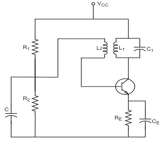
Operation
Once the supply is given, the collector current starts increasing and charging of capacitor C takes place. When the capacitor is fully charged, it discharges through the inductance L1. Now oscillations are produced. These oscillations induce some voltage in the secondary winding L2. The frequency of voltage induced in the secondary winding is same as that of the tank circuit and its magnitude depends upon the number of turns in secondary winding and coupling between both the windings.
The voltage across L2 is applied between base and emitter and appears in the amplified form in the collector circuit, thus overcoming the losses in the tank circuit. The number of turns of L2 and coupling between L1 and L2 are so adjusted that oscillations across L2 are amplified to a level just sufficient to supply losses to the tank circuit.
Tuned collector oscillators are widely used as the local oscillator in radio receivers.
Tuned Base Oscillator
Tuned base oscillators are called so, because the tuned circuit is placed in the base of the transistor amplifier. The combination of L and C form the tuned circuit or frequency determining circuit.
Construction
The resistors R1, R2 and RE are used to provide d.c. bias to the transistor. The parallel combination of Re and Ce in the emitter circuit is the stabilizing circuit. CC is the blocking capacitor. The capacitors CE and C are the by-pass capacitors. The primary coil L and the secondary coil L1 of RF transformer provides the required feedback to collector and base circuits.
As the CE configured transistor provides 180o phase shift, another 180o phase shift is provided by the transformer, which makes 360o phase shift between the input and output voltages. The following circuit diagram shows the arrangement of a tuned base oscillator circuit.
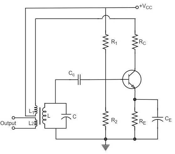
Operation
When the circuit is switched on, the collector current starts rising. As the collector is connected to the coil L1, that current creates some magnetic field around it. This induces a voltage in the tuned circuit coil L. The feedback voltage produces an increase in emitterbase voltage and base current. A further increase in collector current is thus achieved and the cycle continues until the collector current becomes saturated. In the meanwhile, the capacitor is fully charged.
When the collector current reaches saturation level, there is no feedback voltage in L. As the capacitor has been charged fully, it starts discharging through L. This decreases the emitter base bias and hence IB and the collector current also decreases. By the time the collector current reaches cutoff, the capacitor C is fully charged with opposite polarity. As the transistor now gets off, the condenser C begins to discharge through L. This increases the emitter-base bias. As a result, the collector current increases.
The cycle repeats so long as enough energy is supplied to meet the losses in L.C. circuit. The frequency of oscillation is equal to the resonant frequency of L.C. circuit.
Drawback
The main drawback of tuned-base oscillator circuit is that, due to the low base-emitter resistance, which appears in shunt with the tuned circuit, the tank circuit gets loaded. This reduces its Q which in turn causes drift in oscillator frequency. Thus stability becomes poorer. Due to this reason, the tuned circuit is not usually connected in base circuit.
To Continue Learning Please Login