- Sinusoidal Oscillators Tutorial
- Sinusoidal Oscillators - Home
- Oscillators - Introduction
- Oscillators - Basic Concepts
- Oscillators - Oscillator Circuit
- Tuned Circuit Oscillators
- Oscillators - Hartley Oscillator
- Oscillators - Colpitts Oscillator
- Oscillators - Clapp Oscillator
- Oscillators - Phase Shift Oscillators
- Wien Bridge Oscillator
- Oscillators - Crystal Oscillators
- Negative Resistance Oscillators
- Oscillators - Tunnel Diode Oscillator
- Sinusoidal Oscillators Resources
- Sinusoidal Oscillators - Quick Guide
- Sinusoidal Oscillators - Resources
- Sinusoidal Oscillators - Discussion
Sinusoidal Oscillators - Basic Concepts
An amplifier with positive feedback produces its output to be in phase with the input and increases the strength of the signal. Positive feedback is also called as degenerative feedback or direct feedback. This kind of feedback makes a feedback amplifier, an oscillator.
The use of positive feedback results in a feedback amplifier having closed-loop gain greater than the open-loop gain. It results in instability and operates as an oscillatory circuit. An oscillatory circuit provides a constantly varying amplified output signal of any desired frequency.
The Oscillatory Circuit
An oscillatory circuit produces electrical oscillations of a desired frequency. They are also known as tank circuits.
A simple tank circuit comprises of an inductor L and a capacitor C both of which together determine the oscillatory frequency of the circuit.
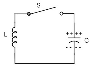
To understand the concept of oscillatory circuit, let us consider the following circuit. The capacitor in this circuit is already charged using a dc source. In this situation, the upper plate of the capacitor has excess of electrons whereas the lower plate has deficit of electrons. The capacitor holds some electrostatic energy and there is a voltage across the capacitor.
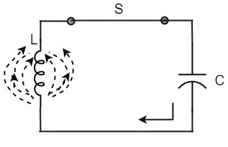
When the switch S is closed, the capacitor discharges and the current flows through the inductor. Due to the inductive effect, the current builds up slowly towards a maximum value. Once the capacitor discharges completely, the magnetic field around the coil is maximum.
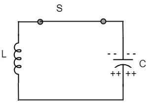
Now, let us move on to the next stage. Once the capacitor is discharged completely, the magnetic field begins to collapse and produces a counter EMF according to Lenz’s law. The capacitor is now charged with positive charge on the upper plate and negative charge on the lower plate.
Once the capacitor is fully charged, it starts to discharge to build up a magnetic field around the coil, as shown in the following circuit diagram.
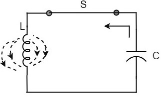
This continuation of charging and discharging results in alternating motion of electrons or an oscillatory current. The interchange of energy between L and C produce continuous oscillations.
In an ideal circuit, where there are no losses, the oscillations would continue indefinitely. In a practical tank circuit, there occur losses such as resistive and radiation losses in the coil and dielectric losses in the capacitor. These losses result in damped oscillations.
Frequency of Oscillations
The frequency of the oscillations produced by the tank circuit are determined by the components of the tank circuit, the L and the C. The actual frequency of oscillations is the resonant frequency (or natural frequency) of the tank circuit which is given by
$$f_r = \frac{1}{2 \pi \sqrt{LC}}$$
Capacitance of the capacitor
The frequency of oscillation fo is inversely proportional to the square root of the capacitance of a capacitor. So, if the value of the capacitor used is large, the charge and discharge time periods will be large. Hence the frequency will be lower.
Mathematically, the frequency,
$$f_o \propto 1\sqrt{C}$$
Self-Inductance of the coil
The frequency of the oscillation fo is proportional to the square root of the self-inductance of the coil. If the value of the inductance is large, the opposition to change of current flow is greater and hence the time required to complete each cycle will be longer, which means time period will be longer and frequency will be lower.
Mathematically, the frequency,
$$f_o \propto 1\sqrt{L}$$
Combining both the above equations,
$$f_o \propto \frac{1}{\sqrt{LC}}$$
$$f_o = \frac{1}{2 \pi \sqrt{LC}}$$
The above equation, though indicates the output frequency, matches the natural frequency or resonance frequency of the tank circuit.
To Continue Learning Please Login