- DCN Tutorial
- Data Comm & Networks Home
- DCN - Overview
- DCN - Computer Network Types
- DCN - Network LAN Technologies
- DCN - Computer Network Topologies
- DCN - Computer Network Models
- DCN - Computer Network Security
- Physical Layer
- DCN - Physical Layer Introduction
- DCN - Digital Transmission
- DCN - Analog Transmission
- DCN - Transmission media
- DCN - Wireless Transmission
- DCN - Multiplexing
- DCN - Network Switching
- Data Link Layer
- DCN - Data Link Layer Introduction
- DCN - Error detection and Correction
- DCN - Data Link Control & Protocols
- Network Layer
- DCN - Network Layer Introduction
- DCN - Network Addressing
- DCN - Routing
- DCN - Internetworking
- DCN - Network Layer Protocols
- Transport Layer
- DCN - Transport Layer Introduction
- DCN - Transmission Control Protocol
- DCN - User Datagram Protocol
- Application Layer
- DCN - Application Layer Introduction
- DCN - Client-Server Model
- DCN - Application Protocols
- DCN - Network Services
- DCN Useful Resources
- DCN - Quick Guide
- DCN - Useful Resources
Computer Network Quick Guide
Data Communication Overview
A system of interconnected computers and computerized peripherals such as printers is called computer network. This interconnection among computers facilitates information sharing among them. Computers may connect to each other by either wired or wireless media.
Classification of Computer Networks
Computer networks are classified based on various factors.They includes:
- Geographical span
- Inter-connectivity
- Administration
- Architecture
Geographical Span
Geographically a network can be seen in one of the following categories:
- It may be spanned across your table, among Bluetooth enabled devices,. Ranging not more than few meters.
- It may be spanned across a whole building, including intermediate devices to connect all floors.
- It may be spanned across a whole city.
- It may be spanned across multiple cities or provinces.
- It may be one network covering whole world.
Inter-Connectivity
Components of a network can be connected to each other differently in some fashion. By connectedness we mean either logically , physically , or both ways.
- Every single device can be connected to every other device on network, making the network mesh.
- All devices can be connected to a single medium but geographically disconnected, created bus like structure.
- Each device is connected to its left and right peers only, creating linear structure.
- All devices connected together with a single device, creating star like structure.
- All devices connected arbitrarily using all previous ways to connect each other, resulting in a hybrid structure.
Administration
From an administrator’s point of view, a network can be private network which belongs a single autonomous system and cannot be accessed outside its physical or logical domain.A network can be public which is accessed by all.
Network Architecture
- There can be one or more systems acting as Server. Other being Client, requests the Server to serve requests.Server takes and processes request on behalf of Clients.
- Two systems can be connected Point-to-Point, or in back-to-back fashion. They both reside at the same level and called peers.
- There can be hybrid network which involves network architecture of both the above types.
Computer networks can be discriminated into various types such as Client-Server,peer-to-peer or hybrid, depending upon its architecture.
Network Applications
Computer systems and peripherals are connected to form a network.They provide numerous advantages:
- Resource sharing such as printers and storage devices
- Exchange of information by means of e-Mails and FTP
- Information sharing by using Web or Internet
- Interaction with other users using dynamic web pages
- IP phones
- Video conferences
- Parallel computing
- Instant messaging
Computer Network Types
Generally, networks are distinguished based on their geographical span. A network can be as small as distance between your mobile phone and its Bluetooth headphone and as large as the internet itself, covering the whole geographical world,
Personal Area Network
A Personal Area Network (PAN) is smallest network which is very personal to a user. This may include Bluetooth enabled devices or infra-red enabled devices. PAN has connectivity range up to 10 meters. PAN may include wireless computer keyboard and mouse, Bluetooth enabled headphones, wireless printers and TV remotes.
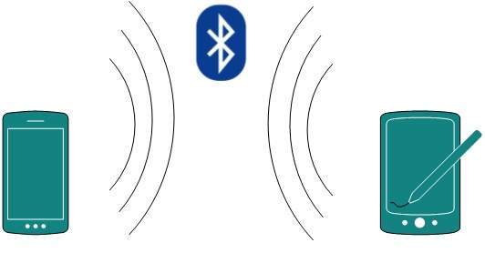
For example, Piconet is Bluetooth-enabled Personal Area Network which may contain up to 8 devices connected together in a master-slave fashion.
Local Area Network
A computer network spanned inside a building and operated under single administrative system is generally termed as Local Area Network (LAN). Usually,LAN covers an organization’ offices, schools, colleges or universities. Number of systems connected in LAN may vary from as least as two to as much as 16 million.
LAN provides a useful way of sharing the resources between end users.The resources such as printers, file servers, scanners, and internet are easily sharable among computers.
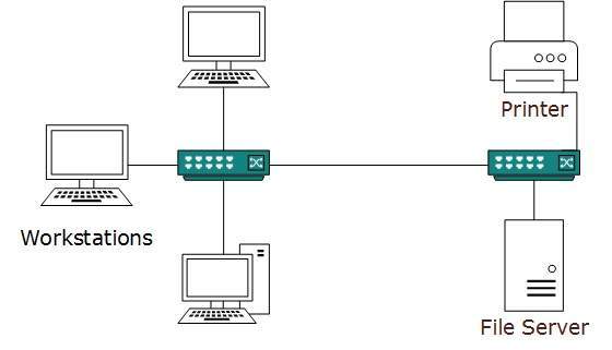
LANs are composed of inexpensive networking and routing equipment. It may contains local servers serving file storage and other locally shared applications. It mostly operates on private IP addresses and does not involve heavy routing. LAN works under its own local domain and controlled centrally.
LAN uses either Ethernet or Token-ring technology. Ethernet is most widely employed LAN technology and uses Star topology, while Token-ring is rarely seen.
LAN can be wired,wireless, or in both forms at once.
Metropolitan Area Network
The Metropolitan Area Network (MAN) generally expands throughout a city such as cable TV network. It can be in the form of Ethernet,Token-ring, ATM, or Fiber Distributed Data Interface (FDDI).
Metro Ethernet is a service which is provided by ISPs. This service enables its users to expand their Local Area Networks. For example, MAN can help an organization to connect all of its offices in a city.
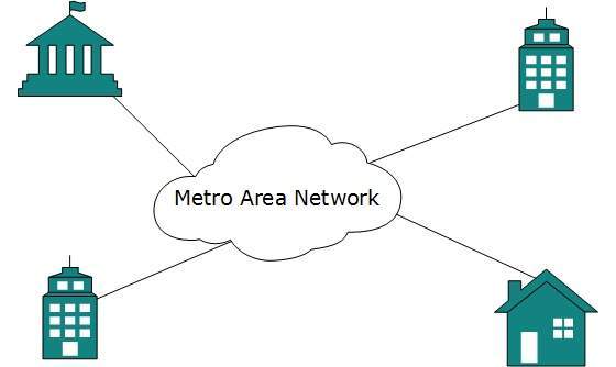
Backbone of MAN is high-capacity and high-speed fiber optics. MAN works in between Local Area Network and Wide Area Network. MAN provides uplink for LANs to WANs or internet.
Wide Area Network
As the name suggests,the Wide Area Network (WAN) covers a wide area which may span across provinces and even a whole country. Generally, telecommunication networks are Wide Area Network. These networks provide connectivity to MANs and LANs. Since they are equipped with very high speed backbone, WANs use very expensive network equipment.
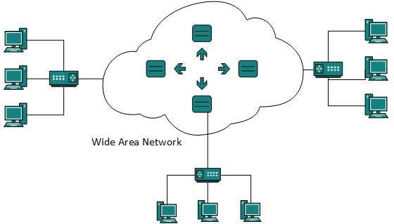
WAN may use advanced technologies such as Asynchronous Transfer Mode (ATM), Frame Relay, and Synchronous Optical Network (SONET). WAN may be managed by multiple administration.
Internetwork
A network of networks is called an internetwork, or simply the internet. It is the largest network in existence on this planet.The internet hugely connects all WANs and it can have connection to LANs and Home networks. Internet uses TCP/IP protocol suite and uses IP as its addressing protocol. Present day, Internet is widely implemented using IPv4. Because of shortage of address spaces, it is gradually migrating from IPv4 to IPv6.
Internet enables its users to share and access enormous amount of information worldwide. It uses WWW, FTP, email services, audio and video streaming etc. At huge level, internet works on Client-Server model.
Internet uses very high speed backbone of fiber optics. To inter-connect various continents, fibers are laid under sea known to us as submarine communication cable.
Internet is widely deployed on World Wide Web services using HTML linked pages and is accessible by client software known as Web Browsers. When a user requests a page using some web browser located on some Web Server anywhere in the world, the Web Server responds with the proper HTML page. The communication delay is very low.
Internet is serving many proposes and is involved in many aspects of life. Some of them are:
- Web sites
- Instant Messaging
- Blogging
- Social Media
- Marketing
- Networking
- Resource Sharing
- Audio and Video Streaming
Network LAN Technologies
Let us go through various LAN technologies in brief:
Ethernet
Ethernet is a widely deployed LAN technology.This technology was invented by Bob Metcalfe and D.R. Boggs in the year 1970. It was standardized in IEEE 802.3 in 1980.
Ethernet shares media. Network which uses shared media has high probability of data collision. Ethernet uses Carrier Sense Multi Access/Collision Detection (CSMA/CD) technology to detect collisions. On the occurrence of collision in Ethernet, all its hosts roll back, wait for some random amount of time, and then re-transmit the data.
Ethernet connector is,network interface card equipped with 48-bits MAC address. This helps other Ethernet devices to identify and communicate with remote devices in Ethernet.
Traditional Ethernet uses 10BASE-T specifications.The number 10 depicts 10MBPS speed, BASE stands for baseband, and T stands for Thick Ethernet. 10BASE-T Ethernet provides transmission speed up to 10MBPS and uses coaxial cable or Cat-5 twisted pair cable with RJ-45 connector. Ethernet follows star topology with segment length up to 100 meters. All devices are connected to a hub/switch in a star fashion.
Fast-Ethernet
To encompass need of fast emerging software and hardware technologies, Ethernet extends itself as Fast-Ethernet. It can run on UTP, Optical Fiber, and wirelessly too. It can provide speed up to 100 MBPS. This standard is named as 100BASE-T in IEEE 803.2 using Cat-5 twisted pair cable. It uses CSMA/CD technique for wired media sharing among the Ethernet hosts and CSMA/CA (CA stands for Collision Avoidance) technique for wireless Ethernet LAN.
Fast Ethernet on fiber is defined under 100BASE-FX standard which provides speed up to 100 MBPS on fiber. Ethernet over fiber can be extended up to 100 meters in half-duplex mode and can reach maximum of 2000 meters in full-duplex over multimode fibers.
Giga-Ethernet
After being introduced in 1995, Fast-Ethernet could enjoy its high speed status only for 3 years till Giga-Ethernet introduced. Giga-Ethernet provides speed up to 1000 mbits/seconds. IEEE802.3ab standardize Giga-Ethernet over UTP using Cat-5, Cat-5e and Cat-6 cables. IEEE802.3ah defines Giga-Ethernet over Fiber.
Virtual LAN
LAN uses Ethernet which in turn works on shared media. Shared media in Ethernet create one single Broadcast domain and one single Collision domain. Introduction of switches to Ethernet has removed single collision domain issue and each device connected to switch works in its separate collision domain. But even Switches cannot divide a network into separate Broadcast domains.
Virtual LAN is a solution to divide a single Broadcast domain into multiple Broadcast domains. Host in one VLAN cannot speak to a host in another. By default, all hosts are placed into the same VLAN.
In this diagram, different VLANs are depicted in different color codes. Hosts in one VLAN, even if connected on the same Switch cannot see or speak to other hosts in different VLANs. VLAN is Layer-2 technology which works closely on Ethernet. To route packets between two different VLANs a Layer-3 device such as Router is required.
Computer Network Toplogies
A Network Topology is the arrangement with which computer systems or network devices are connected to each other. Topologies may define both physical and logical aspect of the network. Both logical and physical topologies could be same or different in a same network.
Point-to-Point
Point-to-point networks contains exactly two hosts such as computer, switches or routers, servers connected back to back using a single piece of cable. Often, the receiving end of one host is connected to sending end of the other and vice-versa.
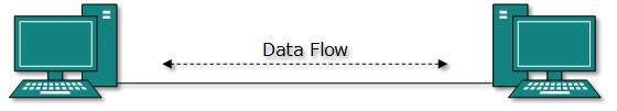
If the hosts are connected point-to-point logically, then may have multiple intermediate devices. But the end hosts are unaware of underlying network and see each other as if they are connected directly.
Bus Topology
In case of Bus topology, all devices share single communication line or cable.Bus topology may have problem while multiple hosts sending data at the same time. Therefore, Bus topology either uses CSMA/CD technology or recognizes one host as Bus Master to solve the issue. It is one of the simple forms of networking where a failure of a device does not affect the other devices. But failure of the shared communication line can make all other devices stop functioning.
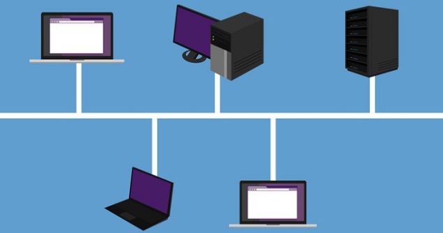
Both ends of the shared channel have line terminator. The data is sent in only one direction and as soon as it reaches the extreme end, the terminator removes the data from the line.
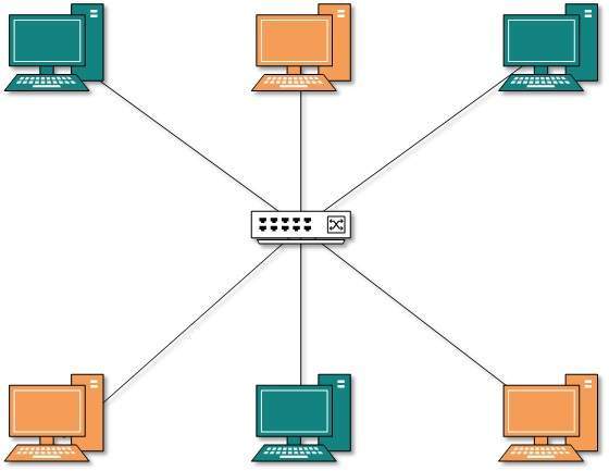
Star Topology
All hosts in Star topology are connected to a central device, known as hub device, using a point-to-point connection. That is, there exists a point to point connection between hosts and hub. The hub device can be any of the following:
- Layer-1 device such as hub or repeater
- Layer-2 device such as switch or bridge
- Layer-3 device such as router or gateway
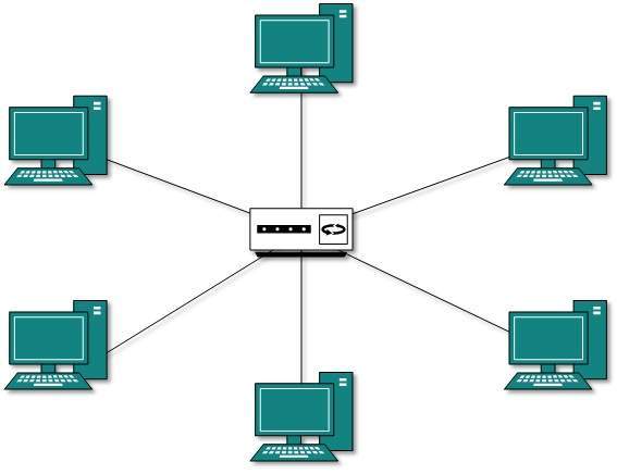
As in Bus topology, hub acts as single point of failure. If hub fails, connectivity of all hosts to all other hosts fails. Every communication between hosts, takes place through only the hub.Star topology is not expensive as to connect one more host, only one cable is required and configuration is simple.
Ring Topology
In ring topology, each host machine connects to exactly two other machines, creating a circular network structure. When one host tries to communicate or send message to a host which is not adjacent to it, the data travels through all intermediate hosts. To connect one more host in the existing structure, the administrator may need only one more extra cable.
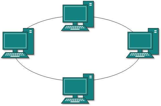
Failure of any host results in failure of the whole ring.Thus, every connection in the ring is a point of failure. There are methods which employ one more backup ring.
Mesh Topology
In this type of topology, a host is connected to one or multiple hosts.This topology has hosts in point-to-point connection with every other host or may also have hosts which are in point-to-point connection to few hosts only.
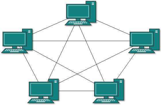
Hosts in Mesh topology also work as relay for other hosts which do not have direct point-to-point links. Mesh technology comes into two types:
- Full Mesh: All hosts have a point-to-point connection to every other host in the network. Thus for every new host n(n-1)/2 connections are required. It provides the most reliable network structure among all network topologies.
- Partially Mesh: Not all hosts have point-to-point connection to every other host. Hosts connect to each other in some arbitrarily fashion. This topology exists where we need to provide reliability to some hosts out of all.
Tree Topology
Also known as Hierarchical Topology, this is the most common form of network topology in use presently.This topology imitates as extended Star topology and inherits properties of bus topology.
This topology divides the network in to multiple levels/layers of network. Mainly in LANs, a network is bifurcated into three types of network devices. The lowermost is access-layer where computers are attached. The middle layer is known as distribution layer, which works as mediator between upper layer and lower layer. The highest layer is known as core layer, and is central point of the network, i.e. root of the tree from which all nodes fork.
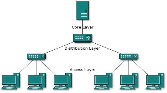
All neighboring hosts have point-to-point connection between them.Similar to the Bus topology, if the root goes down, then the entire network suffers even.though it is not the single point of failure. Every connection serves as point of failure, failing of which divides the network into unreachable segment.
Daisy Chain
This topology connects all the hosts in a linear fashion. Similar to Ring topology, all hosts are connected to two hosts only, except the end hosts.Means, if the end hosts in daisy chain are connected then it represents Ring topology.

Each link in daisy chain topology represents single point of failure. Every link failure splits the network into two segments.Every intermediate host works as relay for its immediate hosts.
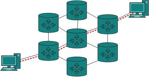
Hybrid Topology
A network structure whose design contains more than one topology is said to be hybrid topology. Hybrid topology inherits merits and demerits of all the incorporating topologies.
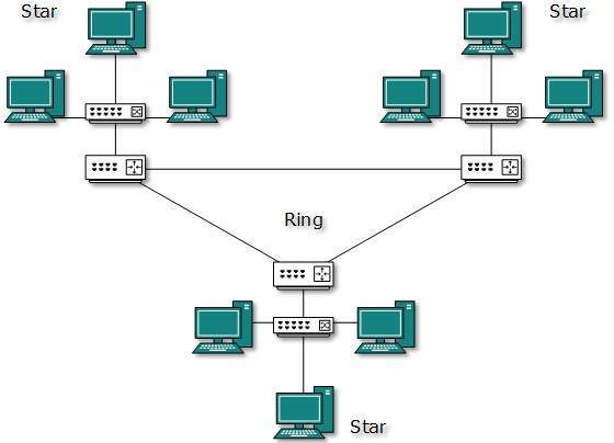
The above picture represents an arbitrarily hybrid topology. The combining topologies may contain attributes of Star, Ring, Bus, and Daisy-chain topologies. Most WANs are connected by means of Dual-Ring topology and networks connected to them are mostly Star topology networks. Internet is the best example of largest Hybrid topology
Computer Network Models
Networking engineering is a complicated task, which involves software, firmware, chip level engineering, hardware, and electric pulses. To ease network engineering, the whole networking concept is divided into multiple layers. Each layer is involved in some particular task and is independent of all other layers. But as a whole, almost all networking tasks depend on all of these layers. Layers share data between them and they depend on each other only to take input and send output.
Layered Tasks
In layered architecture of Network Model, one whole network process is divided into small tasks. Each small task is then assigned to a particular layer which works dedicatedly to process the task only. Every layer does only specific work.
In layered communication system, one layer of a host deals with the task done by or to be done by its peer layer at the same level on the remote host. The task is either initiated by layer at the lowest level or at the top most level. If the task is initiated by the-top most layer, it is passed on to the layer below it for further processing. The lower layer does the same thing, it processes the task and passes on to lower layer. If the task is initiated by lower most layer, then the reverse path is taken.
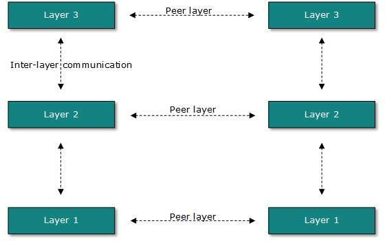
Every layer clubs together all procedures, protocols, and methods which it requires to execute its piece of task. All layers identify their counterparts by means of encapsulation header and tail.
OSI Model
Open System Interconnect is an open standard for all communication systems. OSI model is established by International Standard Organization (ISO). This model has seven layers:
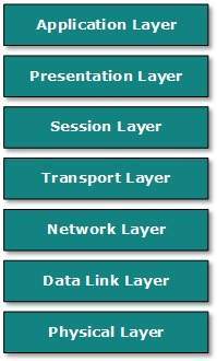
Application Layer: This layer is responsible for providing interface to the application user. This layer encompasses protocols which directly interact with the user.
Presentation Layer: This layer defines how data in the native format of remote host should be presented in the native format of host.
Session Layer: This layer maintains sessions between remote hosts. For example, once user/password authentication is done, the remote host maintains this session for a while and does not ask for authentication again in that time span.
Transport Layer: This layer is responsible for end-to-end delivery between hosts.
Network Layer: This layer is responsible for address assignment and uniquely addressing hosts in a network.
Data Link Layer: This layer is responsible for reading and writing data from and onto the line. Link errors are detected at this layer.
Physical Layer: This layer defines the hardware, cabling wiring, power output, pulse rate etc.
Internet Model
Internet uses TCP/IP protocol suite, also known as Internet suite. This defines Internet Model which contains four layered architecture. OSI Model is general communication model but Internet Model is what the internet uses for all its communication.The internet is independent of its underlying network architecture so is its Model. This model has the following layers:
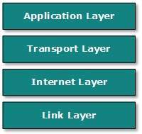
Application Layer: This layer defines the protocol which enables user to interact with the network.For example, FTP, HTTP etc.
Transport Layer: This layer defines how data should flow between hosts. Major protocol at this layer is Transmission Control Protocol (TCP). This layer ensures data delivered between hosts is in-order and is responsible for end-to-end delivery.
Internet Layer: Internet Protocol (IP) works on this layer. This layer facilitates host addressing and recognition. This layer defines routing.
Link Layer: This layer provides mechanism of sending and receiving actual data.Unlike its OSI Model counterpart, this layer is independent of underlying network architecture and hardware.
Computer Network Security
During initial days of internet, its use was limited to military and universities for research and development purpose. Later when all networks merged together and formed internet, the data useds to travel through public transit network.Common people may send the data that can be highly sensitive such as their bank credentials, username and passwords, personal documents, online shopping details, or confidential documents.
All security threats are intentional i.e. they occur only if intentionally triggered. Security threats can be divided into the following categories:
Interruption
Interruption is a security threat in which availability of resources is attacked. For example, a user is unable to access its web-server or the web-server is hijacked.
Privacy-Breach
In this threat, the privacy of a user is compromised. Someone, who is not the authorized person is accessing or intercepting data sent or received by the original authenticated user.
Integrity
This type of threat includes any alteration or modification in the original context of communication. The attacker intercepts and receives the data sent by the sender and the attacker then either modifies or generates false data and sends to the receiver. The receiver receives the data assuming that it is being sent by the original Sender.
Authenticity
This threat occurs when an attacker or a security violator, poses as a genuine person and accesses the resources or communicates with other genuine users.
No technique in the present world can provide 100% security. But steps can be taken to secure data while it travels in unsecured network or internet. The most widely used technique is Cryptography.
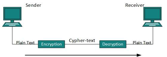
Cryptography is a technique to encrypt the plain-text data which makes it difficult to understand and interpret. There are several cryptographic algorithms available present day as described below:
Secret Key
Public Key
Message Digest
Secret Key Encryption
Both sender and receiver have one secret key. This secret key is used to encrypt the data at sender’s end. After the data is encrypted, it is sent on the public domain to the receiver. Because the receiver knows and has the Secret Key, the encrypted data packets can easily be decrypted.
Example of secret key encryption is Data Encryption Standard (DES). In Secret Key encryption, it is required to have a separate key for each host on the network making it difficult to manage.
Public Key Encryption
In this encryption system, every user has its own Secret Key and it is not in the shared domain. The secret key is never revealed on public domain. Along with secret key, every user has its own but public key. Public key is always made public and is used by Senders to encrypt the data. When the user receives the encrypted data, he can easily decrypt it by using its own Secret Key.
Example of public key encryption is Rivest-Shamir-Adleman (RSA).
Message Digest
In this method, actual data is not sent, instead a hash value is calculated and sent. The other end user, computes its own hash value and compares with the one just received.If both hash values are matched, then it is accepted otherwise rejected.
Example of Message Digest is MD5 hashing. It is mostly used in authentication where user password is cross checked with the one saved on the server.
Physical Layer - Introduction
Physical layer in the OSI model plays the role of interacting with actual hardware and signaling mechanism. Physical layer is the only layer of OSI network model which actually deals with the physical connectivity of two different stations. This layer defines the hardware equipment, cabling, wiring, frequencies, pulses used to represent binary signals etc.
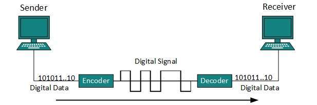
Physical layer provides its services to Data-link layer. Data-link layer hands over frames to physical layer. Physical layer converts them to electrical pulses, which represent binary data.The binary data is then sent over the wired or wireless media.
Signals
When data is sent over physical medium, it needs to be first converted into electromagnetic signals. Data itself can be analog such as human voice, or digital such as file on the disk.Both analog and digital data can be represented in digital or analog signals.
Digital Signals
Digital signals are discrete in nature and represent sequence of voltage pulses. Digital signals are used within the circuitry of a computer system.
Analog Signals
Analog signals are in continuous wave form in nature and represented by continuous electromagnetic waves.
Transmission Impairment
When signals travel through the medium they tend to deteriorate. This may have many reasons as given:
Attenuation
For the receiver to interpret the data accurately, the signal must be sufficiently strong.When the signal passes through the medium, it tends to get weaker.As it covers distance, it loses strength.
Dispersion
As signal travels through the media, it tends to spread and overlaps. The amount of dispersion depends upon the frequency used.
Delay distortion
Signals are sent over media with pre-defined speed and frequency. If the signal speed and frequency do not match, there are possibilities that signal reaches destination in arbitrary fashion. In digital media, this is very critical that some bits reach earlier than the previously sent ones.
Noise
Random disturbance or fluctuation in analog or digital signal is said to be Noise in signal, which may distort the actual information being carried. Noise can be characterized in one of the following class:
Thermal Noise
Heat agitates the electronic conductors of a medium which may introduce noise in the media. Up to a certain level, thermal noise is unavoidable.
Intermodulation
When multiple frequencies share a medium, their interference can cause noise in the medium. Intermodulation noise occurs if two different frequencies are sharing a medium and one of them has excessive strength or the component itself is not functioning properly, then the resultant frequency may not be delivered as expected.
Crosstalk
This sort of noise happens when a foreign signal enters into the media. This is because signal in one medium affects the signal of second medium.
Impulse
This noise is introduced because of irregular disturbances such as lightening, electricity, short-circuit, or faulty components. Digital data is mostly affected by this sort of noise.
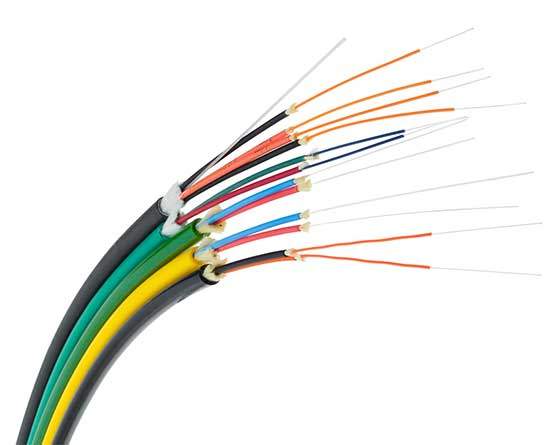
Transmission Media
The media over which the information between two computer systems is sent, called transmission media. Transmission media comes in two forms.
Guided Media
All communication wires/cables are guided media, such as UTP, coaxial cables, and fiber Optics. In this media, the sender and receiver are directly connected and the information is send (guided) through it.
Unguided Media
Wireless or open air space is said to be unguided media, because there is no connectivity between the sender and receiver. Information is spread over the air, and anyone including the actual recipient may collect the information.
Channel Capacity
The speed of transmission of information is said to be the channel capacity. We count it as data rate in digital world. It depends on numerous factors such as:
Bandwidth: The physical limitation of underlying media.
Error-rate: Incorrect reception of information because of noise.
Encoding: The number of levels used for signaling.
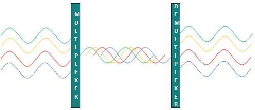
Multiplexing
Multiplexing is a technique to mix and send multiple data streams over a single medium. This technique requires system hardware called multiplexer (MUX) for multiplexing the streams and sending them on a medium, and de-multiplexer (DMUX) which takes information from the medium and distributes to different destinations.
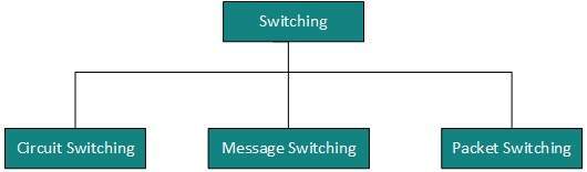
Switching
Switching is a mechanism by which data/information sent from source towards destination which are not directly connected. Networks have interconnecting devices, which receives data from directly connected sources, stores data, analyze it and then forwards to the next interconnecting device closest to the destination.
Switching can be categorized as:
Digital Transmission
Data or information can be stored in two ways, analog and digital. For a computer to use the data, it must be in discrete digital form.Similar to data, signals can also be in analog and digital form. To transmit data digitally, it needs to be first converted to digital form.
Digital-to-Digital Conversion
This section explains how to convert digital data into digital signals. It can be done in two ways, line coding and block coding. For all communications, line coding is necessary whereas block coding is optional.
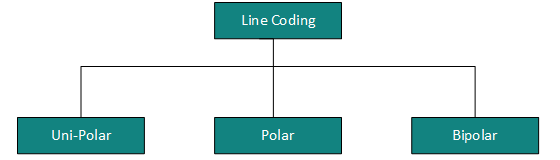
Line Coding
The process for converting digital data into digital signal is said to be Line Coding. Digital data is found in binary format.It is represented (stored) internally as series of 1s and 0s.
Digital signal is denoted by discreet signal, which represents digital data.There are three types of line coding schemes available:
Uni-polar Encoding
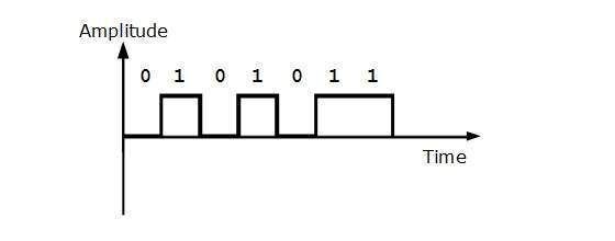
Unipolar encoding schemes use single voltage level to represent data. In this case, to represent binary 1, high voltage is transmitted and to represent 0, no voltage is transmitted. It is also called Unipolar-Non-return-to-zero, because there is no rest condition i.e. it either represents 1 or 0.
Polar Encoding
Polar encoding scheme uses multiple voltage levels to represent binary values. Polar encodings is available in four types:
Polar Non-Return to Zero (Polar NRZ)
It uses two different voltage levels to represent binary values. Generally, positive voltage represents 1 and negative value represents 0. It is also NRZ because there is no rest condition.
NRZ scheme has two variants: NRZ-L and NRZ-I.
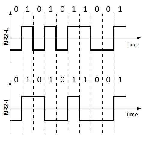
NRZ-L changes voltage level at when a different bit is encountered whereas NRZ-I changes voltage when a 1 is encountered.
Return to Zero (RZ)
Problem with NRZ is that the receiver cannot conclude when a bit ended and when the next bit is started, in case when sender and receiver’s clock are not synchronized.
RZ uses three voltage levels, positive voltage to represent 1, negative voltage to represent 0 and zero voltage for none. Signals change during bits not between bits.
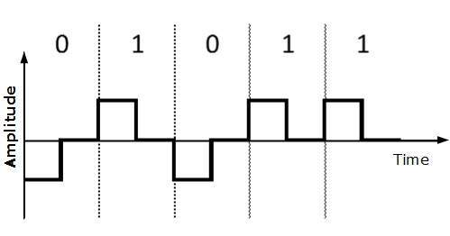
Manchester
This encoding scheme is a combination of RZ and NRZ-L. Bit time is divided into two halves. It transits in the middle of the bit and changes phase when a different bit is encountered.
Differential Manchester
This encoding scheme is a combination of RZ and NRZ-I. It also transit at the middle of the bit but changes phase only when 1 is encountered.
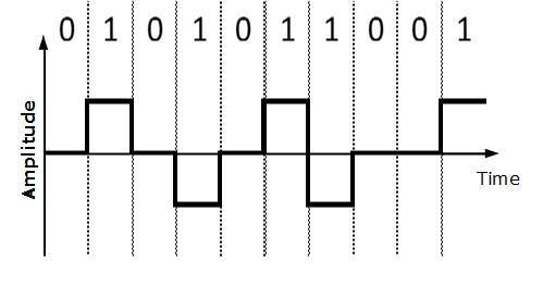
Bipolar Encoding
Bipolar encoding uses three voltage levels, positive, negative and zero. Zero voltage represents binary 0 and bit 1 is represented by altering positive and negative voltages.
Block Coding
To ensure accuracy of the received data frame redundant bits are used. For example, in even-parity, one parity bit is added to make the count of 1s in the frame even. This way the original number of bits is increased. It is called Block Coding.
Block coding is represented by slash notation, mB/nB.Means, m-bit block is substituted with n-bit block where n > m. Block coding involves three steps:
- Division,
- Substitution
- Combination.
After block coding is done, it is line coded for transmission.
Analog-to-Digital Conversion
Microphones create analog voice and camera creates analog videos, which are treated is analog data. To transmit this analog data over digital signals, we need analog to digital conversion.
Analog data is a continuous stream of data in the wave form whereas digital data is discrete. To convert analog wave into digital data, we use Pulse Code Modulation (PCM).
PCM is one of the most commonly used method to convert analog data into digital form. It involves three steps:
- Sampling
- Quantization
- Encoding.
Sampling
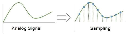
The analog signal is sampled every T interval. Most important factor in sampling is the rate at which analog signal is sampled. According to Nyquist Theorem, the sampling rate must be at least two times of the highest frequency of the signal.
Quantization
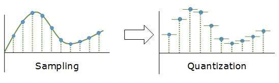
Sampling yields discrete form of continuous analog signal. Every discrete pattern shows the amplitude of the analog signal at that instance. The quantization is done between the maximum amplitude value and the minimum amplitude value. Quantization is approximation of the instantaneous analog value.
Encoding
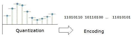
In encoding, each approximated value is then converted into binary format.
Transmission Modes
The transmission mode decides how data is transmitted between two computers.The binary data in the form of 1s and 0s can be sent in two different modes: Parallel and Serial.
Parallel Transmission
The binary bits are organized in-to groups of fixed length. Both sender and receiver are connected in parallel with the equal number of data lines. Both computers distinguish between high order and low order data lines. The sender sends all the bits at once on all lines.Because the data lines are equal to the number of bits in a group or data frame, a complete group of bits (data frame) is sent in one go. Advantage of Parallel transmission is high speed and disadvantage is the cost of wires, as it is equal to the number of bits sent in parallel.
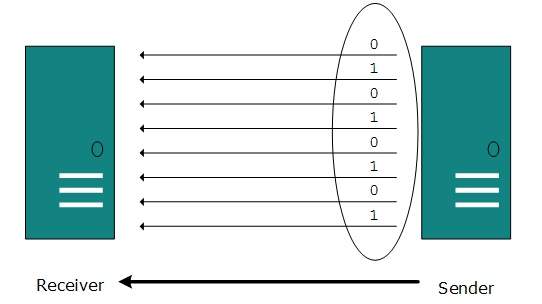
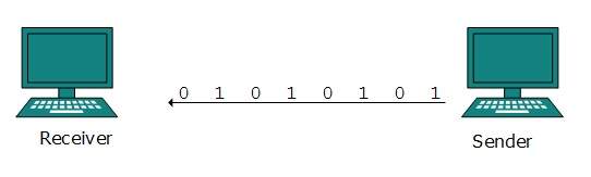
Serial Transmission
In serial transmission, bits are sent one after another in a queue manner. Serial transmission requires only one communication channel.
Serial transmission can be either asynchronous or synchronous.
Asynchronous Serial Transmission
It is named so because there’is no importance of timing. Data-bits have specific pattern and they help receiver recognize the start and end data bits.For example, a 0 is prefixed on every data byte and one or more 1s are added at the end.
Two continuous data-frames (bytes) may have a gap between them.
Synchronous Serial Transmission
Timing in synchronous transmission has importance as there is no mechanism followed to recognize start and end data bits.There is no pattern or prefix/suffix method. Data bits are sent in burst mode without maintaining gap between bytes (8-bits). Single burst of data bits may contain a number of bytes. Therefore, timing becomes very important.
It is up to the receiver to recognize and separate bits into bytes.The advantage of synchronous transmission is high speed, and it has no overhead of extra header and footer bits as in asynchronous transmission.
Analog Transmission
To send the digital data over an analog media, it needs to be converted into analog signal.There can be two cases according to data formatting.
Bandpass:The filters are used to filter and pass frequencies of interest. A bandpass is a band of frequencies which can pass the filter.
Low-pass: Low-pass is a filter that passes low frequencies signals.
When digital data is converted into a bandpass analog signal, it is called digital-to-analog conversion. When low-pass analog signal is converted into bandpass analog signal, it is called analog-to-analog conversion.
Digital-to-Analog Conversion
When data from one computer is sent to another via some analog carrier, it is first converted into analog signals. Analog signals are modified to reflect digital data.
An analog signal is characterized by its amplitude, frequency, and phase. There are three kinds of digital-to-analog conversions:
Amplitude Shift Keying
In this conversion technique, the amplitude of analog carrier signal is modified to reflect binary data.
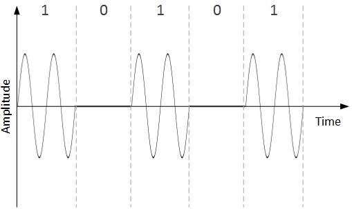
When binary data represents digit 1, the amplitude is held; otherwise it is set to 0. Both frequency and phase remain same as in the original carrier signal.
Frequency Shift Keying
In this conversion technique, the frequency of the analog carrier signal is modified to reflect binary data.
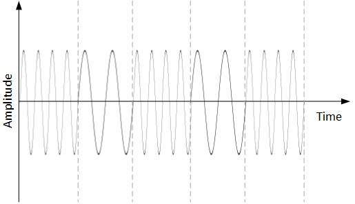
This technique uses two frequencies, f1 and f2. One of them, for example f1, is chosen to represent binary digit 1 and the other one is used to represent binary digit 0. Both amplitude and phase of the carrier wave are kept intact.
Phase Shift Keying
In this conversion scheme, the phase of the original carrier signal is altered to reflect the binary data.
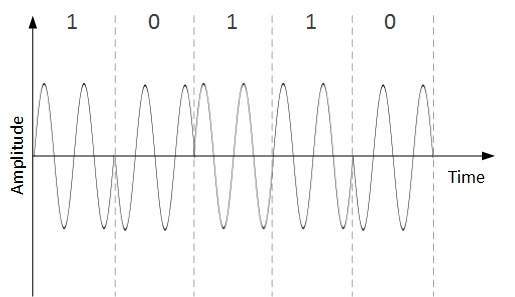
When a new binary symbol is encountered, the phase of the signal is altered. Amplitude and frequency of the original carrier signal is kept intact.
Quadrature Phase Shift Keying
QPSK alters the phase to reflect two binary digits at once. This is done in two different phases. The main stream of binary data is divided equally into two sub-streams. The serial data is converted in to parallel in both sub-streams and then each stream is converted to digital signal using NRZ technique. Later, both the digital signals are merged together.
Analog-to-Analog Conversion
Analog signals are modified to represent analog data. This conversion is also known as Analog Modulation. Analog modulation is required when bandpass is used. Analog to analog conversion can be done in three ways:
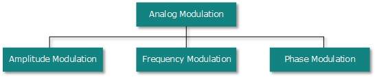
Amplitude Modulation
In this modulation, the amplitude of the carrier signal is modified to reflect the analog data.
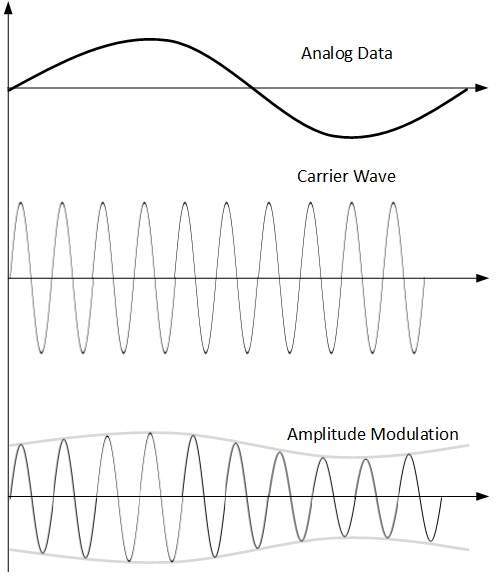
Amplitude modulation is implemented by means of a multiplier. The amplitude of modulating signal (analog data) is multiplied by the amplitude of carrier frequency, which then reflects analog data.
The frequency and phase of carrier signal remain unchanged.
Frequency Modulation
In this modulation technique, the frequency of the carrier signal is modified to reflect the change in the voltage levels of the modulating signal (analog data).
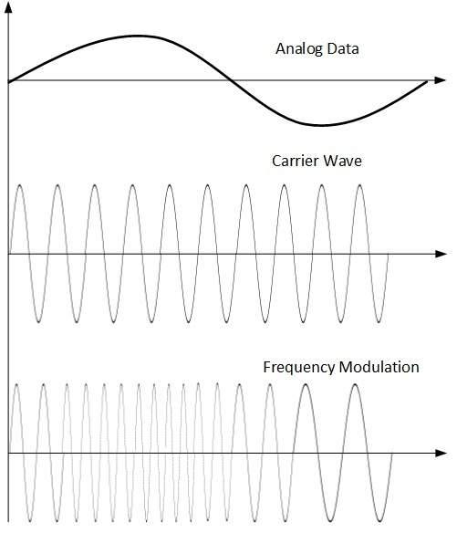
The amplitude and phase of the carrier signal are not altered.
Phase Modulation
In the modulation technique, the phase of carrier signal is modulated in order to reflect the change in voltage (amplitude) of analog data signal.
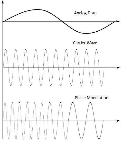
Phase modulation is practically similar to Frequency Modulation, but in Phase modulation frequency of the carrier signal is not increased. Frequency of carrier is signal is changed (made dense and sparse) to reflect voltage change in the amplitude of modulating signal.
Transmission Media
The transmission media is nothing but the physical media over which communication takes place in computer networks.
Magnetic Media
One of the most convenient way to transfer data from one computer to another, even before the birth of networking, was to save it on some storage media and transfer physical from one station to another. Though it may seem old-fashion way in today’s world of high speed internet, but when the size of data is huge, the magnetic media comes into play.
For example, a bank has to handle and transfer huge data of its customer, which stores a backup of it at some geographically far-away place for security reasons and to keep it from uncertain calamities. If the bank needs to store its huge backup data then its,transfer through internet is not feasible.The WAN links may not support such high speed.Even if they do; the cost too high to afford.
In these cases, data backup is stored onto magnetic tapes or magnetic discs, and then shifted physically at remote places.
Twisted Pair Cable
A twisted pair cable is made of two plastic insulated copper wires twisted together to form a single media. Out of these two wires, only one carries actual signal and another is used for ground reference. The twists between wires are helpful in reducing noise (electro-magnetic interference) and crosstalk.

There are two types of twisted pair cables:
Shielded Twisted Pair (STP) Cable
Unshielded Twisted Pair (UTP) Cable
STP cables comes with twisted wire pair covered in metal foil. This makes it more indifferent to noise and crosstalk.
UTP has seven categories, each suitable for specific use. In computer networks, Cat-5, Cat-5e, and Cat-6 cables are mostly used. UTP cables are connected by RJ45 connectors.
Coaxial Cable
Coaxial cable has two wires of copper. The core wire lies in the center and it is made of solid conductor.The core is enclosed in an insulating sheath.The second wire is wrapped around over the sheath and that too in turn encased by insulator sheath.This all is covered by plastic cover.
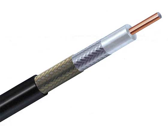
Because of its structure,the coax cable is capable of carrying high frequency signals than that of twisted pair cable.The wrapped structure provides it a good shield against noise and cross talk. Coaxial cables provide high bandwidth rates of up to 450 mbps.
There are three categories of coax cables namely, RG-59 (Cable TV), RG-58 (Thin Ethernet), and RG-11 (Thick Ethernet). RG stands for Radio Government.
Cables are connected using BNC connector and BNC-T. BNC terminator is used to terminate the wire at the far ends.
Power Lines
Power Line communication (PLC) is Layer-1 (Physical Layer) technology which uses power cables to transmit data signals.In PLC, modulated data is sent over the cables. The receiver on the other end de-modulates and interprets the data.
Because power lines are widely deployed, PLC can make all powered devices controlled and monitored. PLC works in half-duplex.
There are two types of PLC:
Narrow band PLC
Broad band PLC
Narrow band PLC provides lower data rates up to 100s of kbps, as they work at lower frequencies (3-5000 kHz).They can be spread over several kilometers.
Broadband PLC provides higher data rates up to 100s of Mbps and works at higher frequencies (1.8 – 250 MHz).They cannot be as much extended as Narrowband PLC.
Fiber Optics
Fiber Optic works on the properties of light. When light ray hits at critical angle it tends to refracts at 90 degree. This property has been used in fiber optic. The core of fiber optic cable is made of high quality glass or plastic. From one end of it light is emitted, it travels through it and at the other end light detector detects light stream and converts it to electric data.
Fiber Optic provides the highest mode of speed. It comes in two modes, one is single mode fiber and second is multimode fiber. Single mode fiber can carry a single ray of light whereas multimode is capable of carrying multiple beams of light.
Fiber Optic also comes in unidirectional and bidirectional capabilities. To connect and access fiber optic special type of connectors are used. These can be Subscriber Channel (SC), Straight Tip (ST), or MT-RJ.
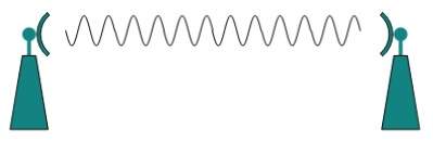
Wireless Transmission
Wireless transmission is a form of unguided media. Wireless communication involves no physical link established between two or more devices, communicating wirelessly. Wireless signals are spread over in the air and are received and interpreted by appropriate antennas.
When an antenna is attached to electrical circuit of a computer or wireless device, it converts the digital data into wireless signals and spread all over within its frequency range. The receptor on the other end receives these signals and converts them back to digital data.
A little part of electromagnetic spectrum can be used for wireless transmission.
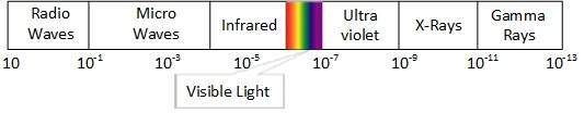
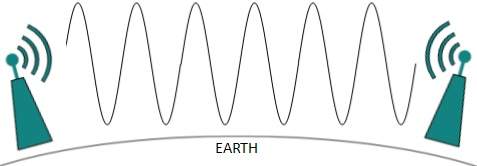
Radio Transmission
Radio frequency is easier to generate and because of its large wavelength it can penetrate through walls and structures alike.Radio waves can have wavelength from 1 mm – 100,000 km and have frequency ranging from 3 Hz (Extremely Low Frequency) to 300 GHz (Extremely High Frequency). Radio frequencies are sub-divided into six bands.
Radio waves at lower frequencies can travel through walls whereas higher RF can travel in straight line and bounce back.The power of low frequency waves decreases sharply as they cover long distance. High frequency radio waves have more power.
Lower frequencies such as VLF, LF, MF bands can travel on the ground up to 1000 kilometers, over the earth’s surface.
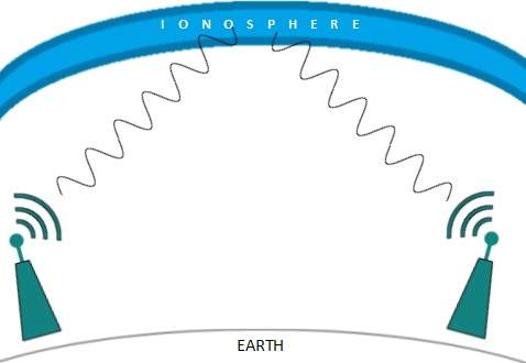
Radio waves of high frequencies are prone to be absorbed by rain and other obstacles. They use Ionosphere of earth atmosphere. High frequency radio waves such as HF and VHF bands are spread upwards. When they reach Ionosphere, they are refracted back to the earth.
Microwave Transmission
Electromagnetic waves above 100 MHz tend to travel in a straight line and signals over them can be sent by beaming those waves towards one particular station. Because Microwaves travels in straight lines, both sender and receiver must be aligned to be strictly in line-of-sight.
Microwaves can have wavelength ranging from 1 mm – 1 meter and frequency ranging from 300 MHz to 300 GHz.
Microwave antennas concentrate the waves making a beam of it. As shown in picture above, multiple antennas can be aligned to reach farther. Microwaves have higher frequencies and do not penetrate wall like obstacles.
Microwave transmission depends highly upon the weather conditions and the frequency it is using.
Infrared Transmission
Infrared wave lies in between visible light spectrum and microwaves. It has wavelength of 700-nm to 1-mm and frequency ranges from 300-GHz to 430-THz.
Infrared wave is used for very short range communication purposes such as television and it’s remote. Infrared travels in a straight line hence it is directional by nature. Because of high frequency range, Infrared cannot cross wall-like obstacles.
Light Transmission
Highest most electromagnetic spectrum which can be used for data transmission is light or optical signaling. This is achieved by means of LASER.
Because of frequency light uses, it tends to travel strictly in straight line.Hence the sender and receiver must be in the line-of-sight. Because laser transmission is unidirectional, at both ends of communication the laser and the photo-detector needs to be installed. Laser beam is generally 1mm wide hence it is a work of precision to align two far receptors each pointing to lasers source.
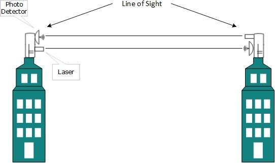
Laser works as Tx (transmitter) and photo-detectors works as Rx (receiver).
Lasers cannot penetrate obstacles such as walls, rain, and thick fog. Additionally, laser beam is distorted by wind, atmosphere temperature, or variation in temperature in the path.
Laser is safe for data transmission as it is very difficult to tap 1mm wide laser without interrupting the communication channel.
Multiplexing
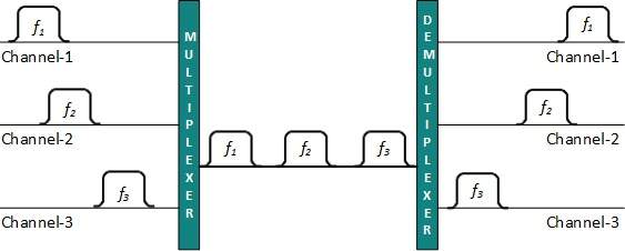
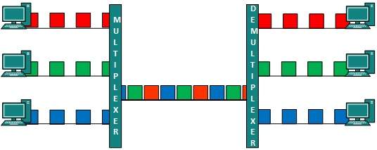
Multiplexing is a technique by which different analog and digital streams of transmission can be simultaneously processed over a shared link. Multiplexing divides the high capacity medium into low capacity logical medium which is then shared by different streams.
Communication is possible over the air (radio frequency), using a physical media (cable), and light (optical fiber). All mediums are capable of multiplexing.
When multiple senders try to send over a single medium, a device called Multiplexer divides the physical channel and allocates one to each. On the other end of communication, a De-multiplexer receives data from a single medium, identifies each, and sends to different receivers.
Frequency Division Multiplexing
When the carrier is frequency, FDM is used. FDM is an analog technology. FDM divides the spectrum or carrier bandwidth in logical channels and allocates one user to each channel. Each user can use the channel frequency independently and has exclusive access of it. All channels are divided in such a way that they do not overlap with each other. Channels are separated by guard bands. Guard band is a frequency which is not used by either channel.
Time Division Multiplexing
TDM is applied primarily on digital signals but can be applied on analog signals as well. In TDM the shared channel is divided among its user by means of time slot. Each user can transmit data within the provided time slot only. Digital signals are divided in frames, equivalent to time slot i.e. frame of an optimal size which can be transmitted in given time slot.
TDM works in synchronized mode. Both ends, i.e. Multiplexer and De-multiplexer are timely synchronized and both switch to next channel simultaneously.
When channel A transmits its frame at one end,the De-multiplexer provides media to channel A on the other end.As soon as the channel A’s time slot expires, this side switches to channel B. On the other end, the De-multiplexer works in a synchronized manner and provides media to channel B. Signals from different channels travel the path in interleaved manner.
Wavelength Division Multiplexing
Light has different wavelength (colors). In fiber optic mode, multiple optical carrier signals are multiplexed into an optical fiber by using different wavelengths. This is an analog multiplexing technique and is done conceptually in the same manner as FDM but uses light as signals.
Further, on each wavelength time division multiplexing can be incorporated to accommodate more data signals.
Code Division Multiplexing
Multiple data signals can be transmitted over a single frequency by using Code Division Multiplexing. FDM divides the frequency in smaller channels but CDM allows its users to full bandwidth and transmit signals all the time using a unique code. CDM uses orthogonal codes to spread signals.
Each station is assigned with a unique code, called chip. Signals travel with these codes independently, inside the whole bandwidth.The receiver knows in advance the chip code signal it has to receive.
Network Switching
Switching is process to forward packets coming in from one port to a port leading towards the destination. When data comes on a port it is called ingress, and when data leaves a port or goes out it is called egress. A communication system may include number of switches and nodes. At broad level, switching can be divided into two major categories:
Connectionless: The data is forwarded on behalf of forwarding tables. No previous handshaking is required and acknowledgements are optional.
Connection Oriented: Before switching data to be forwarded to destination, there is a need to pre-establish circuit along the path between both endpoints. Data is then forwarded on that circuit. After the transfer is completed, circuits can be kept for future use or can be turned down immediately.
Circuit Switching
When two nodes communicate with each other over a dedicated communication path, it is called circuit switching.There 'is a need of pre-specified route from which data will travels and no other data is permitted.In circuit switching, to transfer the data, circuit must be established so that the data transfer can take place.
Circuits can be permanent or temporary. Applications which use circuit switching may have to go through three phases:
Establish a circuit
Transfer the data
Disconnect the circuit
Circuit switching was designed for voice applications. Telephone is the best suitable example of circuit switching. Before a user can make a call, a virtual path between caller and callee is established over the network.
Message Switching
This technique was somewhere in middle of circuit switching and packet switching. In message switching, the whole message is treated as a data unit and is switching / transferred in its entirety.
A switch working on message switching, first receives the whole message and buffers it until there are resources available to transfer it to the next hop. If the next hop is not having enough resource to accommodate large size message, the message is stored and switch waits.
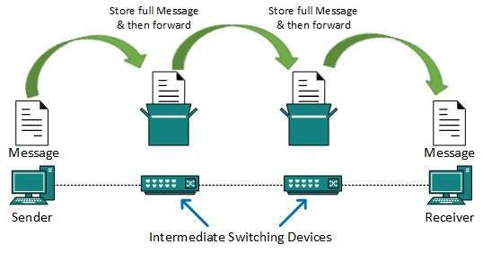
This technique was considered substitute to circuit switching. As in circuit switching the whole path is blocked for two entities only. Message switching is replaced by packet switching. Message switching has the following drawbacks:
Every switch in transit path needs enough storage to accommodate entire message.
Because of store-and-forward technique and waits included until resources are available, message switching is very slow.
Message switching was not a solution for streaming media and real-time applications.
Packet Switching
Shortcomings of message switching gave birth to an idea of packet switching. The entire message is broken down into smaller chunks called packets. The switching information is added in the header of each packet and transmitted independently.
It is easier for intermediate networking devices to store small size packets and they do not take much resources either on carrier path or in the internal memory of switches.
Packet switching enhances line efficiency as packets from multiple applications can be multiplexed over the carrier. The internet uses packet switching technique. Packet switching enables the user to differentiate data streams based on priorities. Packets are stored and forwarded according to their priority to provide quality of service.
Data-link Layer Introduction
Data Link Layer is second layer of OSI Layered Model. This layer is one of the most complicated layers and has complex functionalities and liabilities. Data link layer hides the details of underlying hardware and represents itself to upper layer as the medium to communicate.
Data link layer works between two hosts which are directly connected in some sense. This direct connection could be point to point or broadcast. Systems on broadcast network are said to be on same link. The work of data link layer tends to get more complex when it is dealing with multiple hosts on single collision domain.
Data link layer is responsible for converting data stream to signals bit by bit and to send that over the underlying hardware. At the receiving end, Data link layer picks up data from hardware which are in the form of electrical signals, assembles them in a recognizable frame format, and hands over to upper layer.
Data link layer has two sub-layers:
Logical Link Control: It deals with protocols, flow-control, and error control
Media Access Control: It deals with actual control of media
Functionality of Data-link Layer
Data link layer does many tasks on behalf of upper layer. These are:
Framing
Data-link layer takes packets from Network Layer and encapsulates them into Frames.Then, it sends each frame bit-by-bit on the hardware. At receiver’ end, data link layer picks up signals from hardware and assembles them into frames.
Addressing
Data-link layer provides layer-2 hardware addressing mechanism. Hardware address is assumed to be unique on the link. It is encoded into hardware at the time of manufacturing.
Synchronization
When data frames are sent on the link, both machines must be synchronized in order to transfer to take place.
Error Control
Sometimes signals may have encountered problem in transition and the bits are flipped.These errors are detected and attempted to recover actual data bits. It also provides error reporting mechanism to the sender.
Flow Control
Stations on same link may have different speed or capacity. Data-link layer ensures flow control that enables both machine to exchange data on same speed.
Multi-Access
When host on the shared link tries to transfer the data, it has a high probability of collision. Data-link layer provides mechanism such as CSMA/CD to equip capability of accessing a shared media among multiple Systems.
Error Detection and Correction
There are many reasons such as noise, cross-talk etc., which may help data to get corrupted during transmission. The upper layers work on some generalized view of network architecture and are not aware of actual hardware data processing.Hence, the upper layers expect error-free transmission between the systems. Most of the applications would not function expectedly if they receive erroneous data. Applications such as voice and video may not be that affected and with some errors they may still function well.
Data-link layer uses some error control mechanism to ensure that frames (data bit streams) are transmitted with certain level of accuracy. But to understand how errors is controlled, it is essential to know what types of errors may occur.
Types of Errors
There may be three types of errors:
Single bit error
In a frame, there is only one bit, anywhere though, which is corrupt.
Multiple bits error

Frame is received with more than one bits in corrupted state.
Burst error
Frame contains more than1 consecutive bits corrupted.
Error control mechanism may involve two possible ways:
Error detection
Error correction
Error Detection
Errors in the received frames are detected by means of Parity Check and Cyclic Redundancy Check (CRC). In both cases, few extra bits are sent along with actual data to confirm that bits received at other end are same as they were sent. If the counter-check at receiver’ end fails, the bits are considered corrupted.
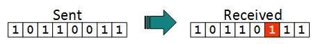
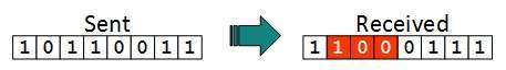
Parity Check
One extra bit is sent along with the original bits to make number of 1s either even in case of even parity, or odd in case of odd parity.
The sender while creating a frame counts the number of 1s in it. For example, if even parity is used and number of 1s is even then one bit with value 0 is added. This way number of 1s remains even.If the number of 1s is odd, to make it even a bit with value 1 is added.
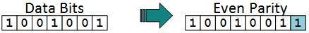
The receiver simply counts the number of 1s in a frame. If the count of 1s is even and even parity is used, the frame is considered to be not-corrupted and is accepted. If the count of 1s is odd and odd parity is used, the frame is still not corrupted.
If a single bit flips in transit, the receiver can detect it by counting the number of 1s. But when more than one bits are erro neous, then it is very hard for the receiver to detect the error.
Cyclic Redundancy Check (CRC)
CRC is a different approach to detect if the received frame contains valid data. This technique involves binary division of the data bits being sent. The divisor is generated using polynomials. The sender performs a division operation on the bits being sent and calculates the remainder. Before sending the actual bits, the sender adds the remainder at the end of the actual bits. Actual data bits plus the remainder is called a codeword. The sender transmits data bits as codewords.
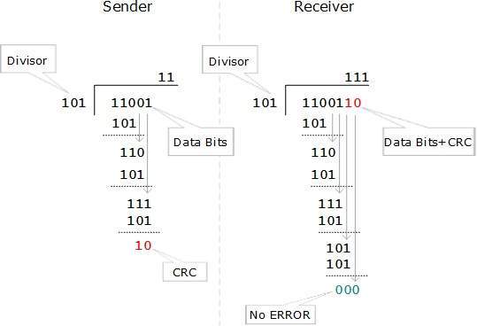
At the other end, the receiver performs division operation on codewords using the same CRC divisor. If the remainder contains all zeros the data bits are accepted, otherwise it is considered as there some data corruption occurred in transit.
Error Correction
In the digital world, error correction can be done in two ways:
Backward Error Correction When the receiver detects an error in the data received, it requests back the sender to retransmit the data unit.
Forward Error Correction When the receiver detects some error in the data received, it executes error-correcting code, which helps it to auto-recover and to correct some kinds of errors.
The first one, Backward Error Correction, is simple and can only be efficiently used where retransmitting is not expensive. For example, fiber optics. But in case of wireless transmission retransmitting may cost too much. In the latter case, Forward Error Correction is used.
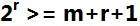
To correct the error in data frame, the receiver must know exactly which bit in the frame is corrupted. To locate the bit in error, redundant bits are used as parity bits for error detection.For example, we take ASCII words (7 bits data), then there could be 8 kind of information we need: first seven bits to tell us which bit is error and one more bit to tell that there is no error.
For m data bits, r redundant bits are used. r bits can provide 2r combinations of information. In m+r bit codeword, there is possibility that the r bits themselves may get corrupted. So the number of r bits used must inform about m+r bit locations plus no-error information, i.e. m+r+1.
Data-link Control and Protocols
Data-link layer is responsible for implementation of point-to-point flow and error control mechanism.
Flow Control
When a data frame (Layer-2 data) is sent from one host to another over a single medium, it is required that the sender and receiver should work at the same speed. That is, sender sends at a speed on which the receiver can process and accept the data. What if the speed (hardware/software) of the sender or receiver differs? If sender is sending too fast the receiver may be overloaded, (swamped) and data may be lost.
Two types of mechanisms can be deployed to control the flow:
Stop and Wait
This flow control mechanism forces the sender after transmitting a data frame to stop and wait until the acknowledgement of the data-frame sent is received.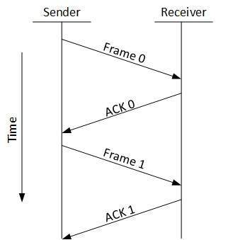
Sliding Window
In this flow control mechanism, both sender and receiver agree on the number of data-frames after which the acknowledgement should be sent. As we learnt, stop and wait flow control mechanism wastes resources, this protocol tries to make use of underlying resources as much as possible.
Error Control
When data-frame is transmitted, there is a probability that data-frame may be lost in the transit or it is received corrupted. In both cases, the receiver does not receive the correct data-frame and sender does not know anything about any loss.In such case, both sender and receiver are equipped with some protocols which helps them to detect transit errors such as loss of data-frame. Hence, either the sender retransmits the data-frame or the receiver may request to resend the previous data-frame.
Requirements for error control mechanism:
Error detection - The sender and receiver, either both or any, must ascertain that there is some error in the transit.
Positive ACK - When the receiver receives a correct frame, it should acknowledge it.
Negative ACK - When the receiver receives a damaged frame or a duplicate frame, it sends a NACK back to the sender and the sender must retransmit the correct frame.
Retransmission: The sender maintains a clock and sets a timeout period. If an acknowledgement of a data-frame previously transmitted does not arrive before the timeout the sender retransmits the frame, thinking that the frame or it’s acknowledgement is lost in transit.
There are three types of techniques available which Data-link layer may deploy to control the errors by Automatic Repeat Requests (ARQ):
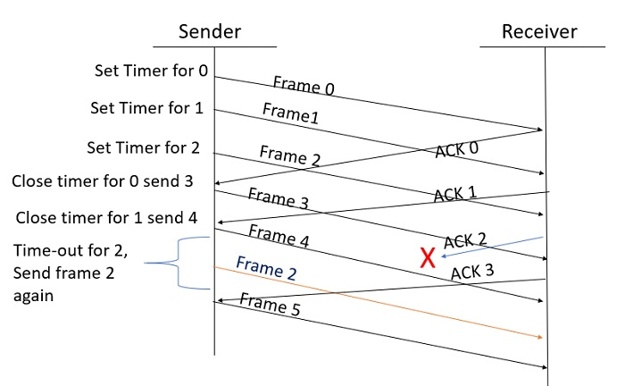
Stop-and-wait ARQ
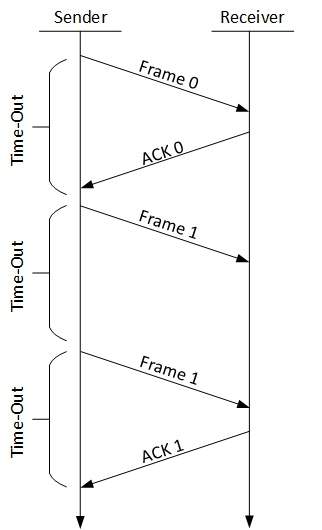
The following transition may occur in Stop-and-Wait ARQ:
- The sender maintains a timeout counter.
- When a frame is sent, the sender starts the timeout counter.
- If acknowledgement of frame comes in time, the sender transmits the next frame in queue.
- If acknowledgement does not come in time, the sender assumes that either the frame or its acknowledgement is lost in transit. Sender retransmits the frame and starts the timeout counter.
- If a negative acknowledgement is received, the sender retransmits the frame.
Go-Back-N ARQ
Stop and wait ARQ mechanism does not utilize the resources at their best.When the acknowledgement is received, the sender sits idle and does nothing. In Go-Back-N ARQ method, both sender and receiver maintain a window.
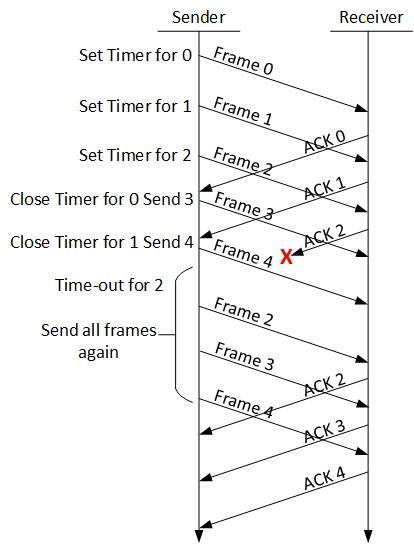
The sending-window size enables the sender to send multiple frames without receiving the acknowledgement of the previous ones. The receiving-window enables the receiver to receive multiple frames and acknowledge them. The receiver keeps track of incoming frame’s sequence number.
When the sender sends all the frames in window, it checks up to what sequence number it has received positive acknowledgement. If all frames are positively acknowledged, the sender sends next set of frames. If sender finds that it has received NACK or has not receive any ACK for a particular frame, it retransmits all the frames after which it does not receive any positive ACK.
Selective Repeat ARQ
In Go-back-N ARQ, it is assumed that the receiver does not have any buffer space for its window size and has to process each frame as it comes. This enforces the sender to retransmit all the frames which are not acknowledged.
In Selective-Repeat ARQ, the receiver while keeping track of sequence numbers, buffers the frames in memory and sends NACK for only frame which is missing or damaged.
The sender in this case, sends only packet for which NACK is received.
Network Layer Introduction
Layer-3 in the OSI model is called Network layer. Network layer manages options pertaining to host and network addressing, managing sub-networks, and internetworking.
Network layer takes the responsibility for routing packets from source to destination within or outside a subnet. Two different subnet may have different addressing schemes or non-compatible addressing types. Same with protocols, two different subnet may be operating on different protocols which are not compatible with each other. Network layer has the responsibility to route the packets from source to destination, mapping different addressing schemes and protocols.
Layer-3 Functionalities
Devices which work on Network Layer mainly focus on routing. Routing may include various tasks aimed to achieve a single goal. These can be:
Addressing devices and networks.
Populating routing tables or static routes.
Queuing incoming and outgoing data and then forwarding them according to quality of service constraints set for those packets.
Internetworking between two different subnets.
Delivering packets to destination with best efforts.
Provides connection oriented and connection less mechanism.
Network Layer Features
With its standard functionalities, Layer 3 can provide various features as:
Quality of service management
Load balancing and link management
Security
Interrelation of different protocols and subnets with different schema.
Different logical network design over the physical network design.
L3 VPN and tunnels can be used to provide end to end dedicated connectivity.
Internet protocol is widely respected and deployed Network Layer protocol which helps to communicate end to end devices over the internet. It comes in two flavors. IPv4 which has ruled the world for decades but now is running out of address space. IPv6 is created to replace IPv4 and hopefully mitigates limitations of IPv4 too.
Network Addressing
Layer 3 network addressing is one of the major tasks of Network Layer. Network Addresses are always logical i.e. these are software based addresses which can be changed by appropriate configurations.
A network address always points to host / node / server or it can represent a whole network. Network address is always configured on network interface card and is generally mapped by system with the MAC address (hardware address or layer-2 address) of the machine for Layer-2 communication.
There are different kinds of network addresses in existence:
IP
IPX
AppleTalk
We are discussing IP here as it is the only one we use in practice these days.
IP addressing provides mechanism to differentiate between hosts and network. Because IP addresses are assigned in hierarchical manner, a host always resides under a specific network.The host which needs to communicate outside its subnet, needs to know destination network address, where the packet/data is to be sent.
Hosts in different subnet need a mechanism to locate each other. This task can be done by DNS. DNS is a server which provides Layer-3 address of remote host mapped with its domain name or FQDN. When a host acquires the Layer-3 Address (IP Address) of the remote host, it forwards all its packet to its gateway. A gateway is a router equipped with all the information which leads to route packets to the destination host.
Routers take help of routing tables, which has the following information:
Method to reach the network
Routers upon receiving a forwarding request, forwards packet to its next hop (adjacent router) towards the destination.
The next router on the path follows the same thing and eventually the data packet reaches its destination.
Network address can be of one of the following:
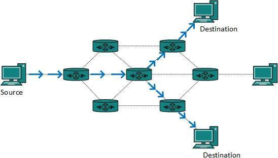
Unicast (destined to one host)
Multicast (destined to group)
Broadcast (destined to all)
Anycast (destined to nearest one)
A router never forwards broadcast traffic by default. Multicast traffic uses special treatment as it is most a video stream or audio with highest priority. Anycast is just similar to unicast, except that the packets are delivered to the nearest destination when multiple destinations are available.
Network Layer Routing
When a device has multiple paths to reach a destination, it always selects one path by preferring it over others. This selection process is termed as Routing. Routing is done by special network devices called routers or it can be done by means of software processes.The software based routers have limited functionality and limited scope.
A router is always configured with some default route. A default route tells the router where to forward a packet if there is no route found for specific destination. In case there are multiple path existing to reach the same destination, router can make decision based on the following information:
Hop Count
Bandwidth
Metric
Prefix-length
Delay
Routes can be statically configured or dynamically learnt. One route can be configured to be preferred over others.
Unicast routing
Most of the traffic on the internet and intranets known as unicast data or unicast traffic is sent with specified destination. Routing unicast data over the internet is called unicast routing. It is the simplest form of routing because the destination is already known. Hence the router just has to look up the routing table and forward the packet to next hop.
Broadcast routing
By default, the broadcast packets are not routed and forwarded by the routers on any network. Routers create broadcast domains. But it can be configured to forward broadcasts in some special cases. A broadcast message is destined to all network devices.
Broadcast routing can be done in two ways (algorithm):
A router creates a data packet and then sends it to each host one by one. In this case, the router creates multiple copies of single data packet with different destination addresses. All packets are sent as unicast but because they are sent to all, it simulates as if router is broadcasting.
This method consumes lots of bandwidth and router must destination address of each node.
Secondly, when router receives a packet that is to be broadcasted, it simply floods those packets out of all interfaces. All routers are configured in the same way.
This method is easy on router's CPU but may cause the problem of duplicate packets received from peer routers.
Reverse path forwarding is a technique, in which router knows in advance about its predecessor from where it should receive broadcast. This technique is used to detect and discard duplicates.
Multicast Routing
Multicast routing is special case of broadcast routing with significance difference and challenges. In broadcast routing, packets are sent to all nodes even if they do not want it. But in Multicast routing, the data is sent to only nodes which wants to receive the packets.
The router must know that there are nodes, which wish to receive multicast packets (or stream) then only it should forward. Multicast routing works spanning tree protocol to avoid looping.
Multicast routing also uses reverse path Forwarding technique, to detect and discard duplicates and loops.
Anycast Routing
Anycast packet forwarding is a mechanism where multiple hosts can have same logical address. When a packet destined to this logical address is received, it is sent to the host which is nearest in routing topology.
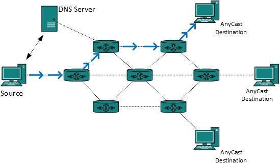
Anycast routing is done with help of DNS server. Whenever an Anycast packet is received it is enquired with DNS to where to send it. DNS provides the IP address which is the nearest IP configured on it.
Unicast Routing Protocols
There are two kinds of routing protocols available to route unicast packets:
Distance Vector Routing Protocol
Distance Vector is simple routing protocol which takes routing decision on the number of hops between source and destination. A route with less number of hops is considered as the best route. Every router advertises its set best routes to other routers. Ultimately, all routers build up their network topology based on the advertisements of their peer routers,
For example Routing Information Protocol (RIP).
Link State Routing Protocol
Link State protocol is slightly complicated protocol than Distance Vector. It takes into account the states of links of all the routers in a network. This technique helps routes build a common graph of the entire network. All routers then calculate their best path for routing purposes.for example, Open Shortest Path First (OSPF) and Intermediate System to Intermediate System (ISIS).
Multicast Routing Protocols
Unicast routing protocols use graphs while Multicast routing protocols use trees, i.e. spanning tree to avoid loops. The optimal tree is called shortest path spanning tree.
DVMRP - Distance Vector Multicast Routing Protocol
MOSPF - Multicast Open Shortest Path First
CBT - Core Based Tree
PIM - Protocol independent Multicast
Protocol Independent Multicast is commonly used now. It has two flavors:
PIM Dense Mode
This mode uses source-based trees. It is used in dense environment such as LAN.
PIM Sparse Mode
This mode uses shared trees. It is used in sparse environment such as WAN.
Routing Algorithms
The routing algorithms are as follows:
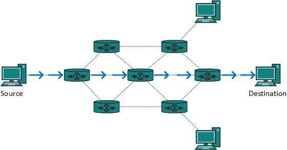
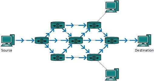
Flooding
Flooding is simplest method packet forwarding. When a packet is received, the routers send it to all the interfaces except the one on which it was received. This creates too much burden on the network and lots of duplicate packets wandering in the network.
Time to Live (TTL) can be used to avoid infinite looping of packets. There exists another approach for flooding, which is called Selective Flooding to reduce the overhead on the network. In this method, the router does not flood out on all the interfaces, but selective ones.
Shortest Path
Routing decision in networks, are mostly taken on the basis of cost between source and destination. Hop count plays major role here. Shortest path is a technique which uses various algorithms to decide a path with minimum number of hops.
Common shortest path algorithms are:
Dijkstra's algorithm
Bellman Ford algorithm
Floyd Warshall algorithm
Internetworking
In real world scenario, networks under same administration are generally scattered geographically. There may exist requirement of connecting two different networks of same kind as well as of different kinds. Routing between two networks is called internetworking.
Networks can be considered different based on various parameters such as, Protocol, topology, Layer-2 network and addressing scheme.
In internetworking, routers have knowledge of each other’s address and addresses beyond them. They can be statically configured go on different network or they can learn by using internetworking routing protocol.
Routing protocols which are used within an organization or administration are called Interior Gateway Protocols or IGP. RIP, OSPF are examples of IGP. Routing between different organizations or administrations may have Exterior Gateway Protocol, and there is only one EGP i.e. Border Gateway Protocol.
Tunneling
If they are two geographically separate networks, which want to communicate with each other, they may deploy a dedicated line between or they have to pass their data through intermediate networks.
Tunneling is a mechanism by which two or more same networks communicate with each other, by passing intermediate networking complexities. Tunneling is configured at both ends.
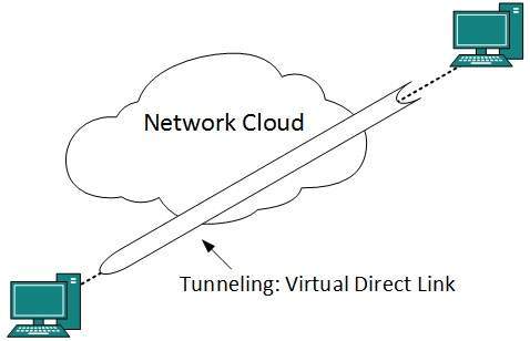
When the data enters from one end of Tunnel, it is tagged. This tagged data is then routed inside the intermediate or transit network to reach the other end of Tunnel. When data exists the Tunnel its tag is removed and delivered to the other part of the network.
Both ends seem as if they are directly connected and tagging makes data travel through transit network without any modifications.
Packet Fragmentation
Most Ethernet segments have their maximum transmission unit (MTU) fixed to 1500 bytes. A data packet can have more or less packet length depending upon the application. Devices in the transit path also have their hardware and software capabilities which tell what amount of data that device can handle and what size of packet it can process.
If the data packet size is less than or equal to the size of packet the transit network can handle, it is processed neutrally. If the packet is larger, it is broken into smaller pieces and then forwarded. This is called packet fragmentation. Each fragment contains the same destination and source address and routed through transit path easily. At the receiving end it is assembled again.
If a packet with DF (don’t fragment) bit set to 1 comes to a router which can not handle the packet because of its length, the packet is dropped.
When a packet is received by a router has its MF (more fragments) bit set to 1, the router then knows that it is a fragmented packet and parts of the original packet is on the way.
If packet is fragmented too small, the overhead is increases. If the packet is fragmented too large, intermediate router may not be able to process it and it might get dropped.
Network Layer Protocols
Every computer in a network has an IP address by which it can be uniquely identified and addressed. An IP address is Layer-3 (Network Layer) logical address. This address may change every time a computer restarts. A computer can have one IP at one instance of time and another IP at some different time.
Address Resolution Protocol(ARP)
While communicating, a host needs Layer-2 (MAC) address of the destination machine which belongs to the same broadcast domain or network. A MAC address is physically burnt into the Network Interface Card (NIC) of a machine and it never changes.
On the other hand, IP address on the public domain is rarely changed. If the NIC is changed in case of some fault, the MAC address also changes. This way, for Layer-2 communication to take place, a mapping between the two is required.
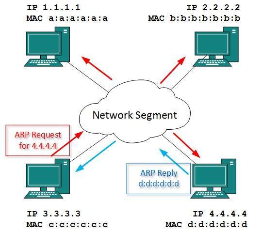
To know the MAC address of remote host on a broadcast domain, a computer wishing to initiate communication sends out an ARP broadcast message asking, “Who has this IP address?” Because it is a broadcast, all hosts on the network segment (broadcast domain) receive this packet and process it. ARP packet contains the IP address of destination host, the sending host wishes to talk to. When a host receives an ARP packet destined to it, it replies back with its own MAC address.
Once the host gets destination MAC address, it can communicate with remote host using Layer-2 link protocol. This MAC to IP mapping is saved into ARP cache of both sending and receiving hosts. Next time, if they require to communicate, they can directly refer to their respective ARP cache.
Reverse ARP is a mechanism where host knows the MAC address of remote host but requires to know IP address to communicate.
Internet Control Message Protocol (ICMP)
ICMP is network diagnostic and error reporting protocol. ICMP belongs to IP protocol suite and uses IP as carrier protocol. After constructing ICMP packet, it is encapsulated in IP packet. Because IP itself is a best-effort non-reliable protocol, so is ICMP.
Any feedback about network is sent back to the originating host. If some error in the network occurs, it is reported by means of ICMP. ICMP contains dozens of diagnostic and error reporting messages.
ICMP-echo and ICMP-echo-reply are the most commonly used ICMP messages to check the reachability of end-to-end hosts. When a host receives an ICMP-echo request, it is bound to send back an ICMP-echo-reply. If there is any problem in the transit network, the ICMP will report that problem.
Internet Protocol Version 4 (IPv4)
IPv4 is 32-bit addressing scheme used as TCP/IP host addressing mechanism. IP addressing enables every host on the TCP/IP network to be uniquely identifiable.
IPv4 provides hierarchical addressing scheme which enables it to divide the network into sub-networks, each with well-defined number of hosts. IP addresses are divided into many categories:
Class A - it uses first octet for network addresses and last three octets for host addressing
Class B - it uses first two octets for network addresses and last two for host addressing
Class C - it uses first three octets for network addresses and last one for host addressing
Class D - it provides flat IP addressing scheme in contrast to hierarchical structure for above three.
Class E - It is used as experimental.
IPv4 also has well-defined address spaces to be used as private addresses (not routable on internet), and public addresses (provided by ISPs and are routable on internet).
Though IP is not reliable one; it provides ‘Best-Effort-Delivery’ mechanism.
Internet Protocol Version 6 (IPv6)
Exhaustion of IPv4 addresses gave birth to a next generation Internet Protocol version 6. IPv6 addresses its nodes with 128-bit wide address providing plenty of address space for future to be used on entire planet or beyond.
IPv6 has introduced Anycast addressing but has removed the concept of broadcasting. IPv6 enables devices to self-acquire an IPv6 address and communicate within that subnet. This auto-configuration removes the dependability of Dynamic Host Configuration Protocol (DHCP) servers. This way, even if the DHCP server on that subnet is down, the hosts can communicate with each other.
IPv6 provides new feature of IPv6 mobility. Mobile IPv6 equipped machines can roam around without the need of changing their IP addresses.
IPv6 is still in transition phase and is expected to replace IPv4 completely in coming years. At present, there are few networks which are running on IPv6. There are some transition mechanisms available for IPv6 enabled networks to speak and roam around different networks easily on IPv4. These are:
- Dual stack implementation
- Tunneling
- NAT-PT
Transport Layer Introduction
Next Layer in OSI Model is recognized as Transport Layer (Layer-4). All modules and procedures pertaining to transportation of data or data stream are categorized into this layer. As all other layers, this layer communicates with its peer Transport layer of the remote host.
Transport layer offers peer-to-peer and end-to-end connection between two processes on remote hosts. Transport layer takes data from upper layer (i.e. Application layer) and then breaks it into smaller size segments, numbers each byte, and hands over to lower layer (Network Layer) for delivery.
Functions
This Layer is the first one which breaks the information data, supplied by Application layer in to smaller units called segments. It numbers every byte in the segment and maintains their accounting.
This layer ensures that data must be received in the same sequence in which it was sent.
This layer provides end-to-end delivery of data between hosts which may or may not belong to the same subnet.
All server processes intend to communicate over the network are equipped with well-known Transport Service Access Points (TSAPs) also known as port numbers.
End-to-End Communication
A process on one host identifies its peer host on remote network by means of TSAPs, also known as Port numbers. TSAPs are very well defined and a process which is trying to communicate with its peer knows this in advance.
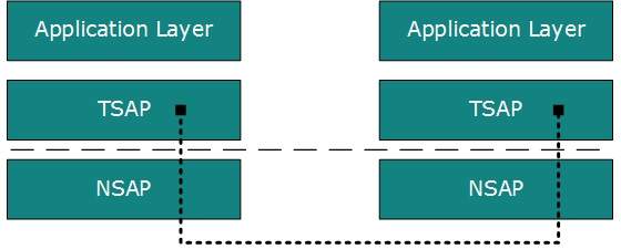
For example, when a DHCP client wants to communicate with remote DHCP server, it always requests on port number 67. When a DNS client wants to communicate with remote DNS server, it always requests on port number 53 (UDP).
The two main Transport layer protocols are:
Transmission Control Protocol
It provides reliable communication between two hosts.
User Datagram Protocol
It provides unreliable communication between two hosts.
Transmission Control Protocol
The transmission Control Protocol (TCP) is one of the most important protocols of Internet Protocols suite. It is most widely used protocol for data transmission in communication network such as internet.
Features
TCP is reliable protocol. That is, the receiver always sends either positive or negative acknowledgement about the data packet to the sender, so that the sender always has bright clue about whether the data packet is reached the destination or it needs to resend it.
TCP ensures that the data reaches intended destination in the same order it was sent.
TCP is connection oriented. TCP requires that connection between two remote points be established before sending actual data.
TCP provides error-checking and recovery mechanism.
TCP provides end-to-end communication.
TCP provides flow control and quality of service.
TCP operates in Client/Server point-to-point mode.
TCP provides full duplex server, i.e. it can perform roles of both receiver and sender.
Header
The length of TCP header is minimum 20 bytes long and maximum 60 bytes.
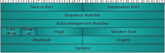
Source Port (16-bits) - It identifies source port of the application process on the sending device.
Destination Port (16-bits) - It identifies destination port of the application process on the receiving device.
Sequence Number (32-bits) - Sequence number of data bytes of a segment in a session.
Acknowledgement Number (32-bits) - When ACK flag is set, this number contains the next sequence number of the data byte expected and works as acknowledgement of the previous data received.
Data Offset (4-bits) - This field implies both, the size of TCP header (32-bit words) and the offset of data in current packet in the whole TCP segment.
Reserved (3-bits) - Reserved for future use and all are set zero by default.
Flags (1-bit each)
NS - Nonce Sum bit is used by Explicit Congestion Notification signaling process.
CWR - When a host receives packet with ECE bit set, it sets Congestion Windows Reduced to acknowledge that ECE received.
ECE -It has two meanings:
If SYN bit is clear to 0, then ECE means that the IP packet has its CE (congestion experience) bit set.
If SYN bit is set to 1, ECE means that the device is ECT capable.
URG - It indicates that Urgent Pointer field has significant data and should be processed.
ACK - It indicates that Acknowledgement field has significance. If ACK is cleared to 0, it indicates that packet does not contain any acknowledgement.
PSH - When set, it is a request to the receiving station to PUSH data (as soon as it comes) to the receiving application without buffering it.
RST - Reset flag has the following features:
It is used to refuse an incoming connection.
It is used to reject a segment.
It is used to restart a connection.
SYN - This flag is used to set up a connection between hosts.
FIN - This flag is used to release a connection and no more data is exchanged thereafter. Because packets with SYN and FIN flags have sequence numbers, they are processed in correct order.
Windows Size - This field is used for flow control between two stations and indicates the amount of buffer (in bytes) the receiver has allocated for a segment, i.e. how much data is the receiver expecting.
Checksum - This field contains the checksum of Header, Data and Pseudo Headers.
Urgent Pointer - It points to the urgent data byte if URG flag is set to 1.
Options - It facilitates additional options which are not covered by the regular header. Option field is always described in 32-bit words. If this field contains data less than 32-bit, padding is used to cover the remaining bits to reach 32-bit boundary.
Addressing
TCP communication between two remote hosts is done by means of port numbers (TSAPs). Ports numbers can range from 0 – 65535 which are divided as:
- System Ports (0 – 1023)
- User Ports ( 1024 – 49151)
- Private/Dynamic Ports (49152 – 65535)
Connection Management
TCP communication works in Server/Client model. The client initiates the connection and the server either accepts or rejects it. Three-way handshaking is used for connection management.
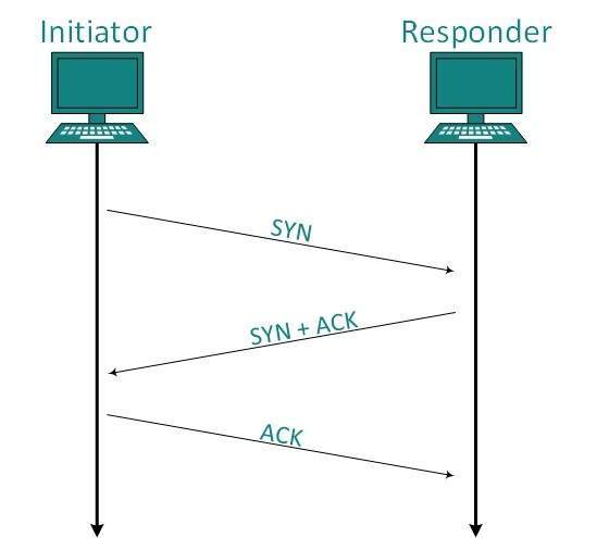
Establishment
Client initiates the connection and sends the segment with a Sequence number. Server acknowledges it back with its own Sequence number and ACK of client’s segment which is one more than client’s Sequence number. Client after receiving ACK of its segment sends an acknowledgement of Server’s response.
Release
Either of server and client can send TCP segment with FIN flag set to 1. When the receiving end responds it back by ACKnowledging FIN, that direction of TCP communication is closed and connection is released.
Bandwidth Management
TCP uses the concept of window size to accommodate the need of Bandwidth management. Window size tells the sender at the remote end, the number of data byte segments the receiver at this end can receive. TCP uses slow start phase by using window size 1 and increases the window size exponentially after each successful communication.
For example, the client uses windows size 2 and sends 2 bytes of data. When the acknowledgement of this segment received the windows size is doubled to 4 and next sent the segment sent will be 4 data bytes long. When the acknowledgement of 4-byte data segment is received, the client sets windows size to 8 and so on.
If an acknowledgement is missed, i.e. data lost in transit network or it received NACK, then the window size is reduced to half and slow start phase starts again.
Error Control &and Flow Control
TCP uses port numbers to know what application process it needs to handover the data segment. Along with that, it uses sequence numbers to synchronize itself with the remote host. All data segments are sent and received with sequence numbers. The Sender knows which last data segment was received by the Receiver when it gets ACK. The Receiver knows about the last segment sent by the Sender by referring to the sequence number of recently received packet.
If the sequence number of a segment recently received does not match with the sequence number the receiver was expecting, then it is discarded and NACK is sent back. If two segments arrive with the same sequence number, the TCP timestamp value is compared to make a decision.
Multiplexing
The technique to combine two or more data streams in one session is called Multiplexing. When a TCP client initializes a connection with Server, it always refers to a well-defined port number which indicates the application process. The client itself uses a randomly generated port number from private port number pools.
Using TCP Multiplexing, a client can communicate with a number of different application process in a single session. For example, a client requests a web page which in turn contains different types of data (HTTP, SMTP, FTP etc.) the TCP session timeout is increased and the session is kept open for longer time so that the three-way handshake overhead can be avoided.
This enables the client system to receive multiple connection over single virtual connection. These virtual connections are not good for Servers if the timeout is too long.
Congestion Control
When large amount of data is fed to system which is not capable of handling it, congestion occurs. TCP controls congestion by means of Window mechanism. TCP sets a window size telling the other end how much data segment to send. TCP may use three algorithms for congestion control:
Additive increase, Multiplicative Decrease
Slow Start
Timeout React
Timer Management
TCP uses different types of timer to control and management various tasks:
Keep-alive timer:
This timer is used to check the integrity and validity of a connection.
When keep-alive time expires, the host sends a probe to check if the connection still exists.
Retransmission timer:
This timer maintains stateful session of data sent.
If the acknowledgement of sent data does not receive within the Retransmission time, the data segment is sent again.
Persist timer:
TCP session can be paused by either host by sending Window Size 0.
To resume the session a host needs to send Window Size with some larger value.
If this segment never reaches the other end, both ends may wait for each other for infinite time.
When the Persist timer expires, the host re-sends its window size to let the other end know.
Persist Timer helps avoid deadlocks in communication.
Timed-Wait:
After releasing a connection, either of the hosts waits for a Timed-Wait time to terminate the connection completely.
This is in order to make sure that the other end has received the acknowledgement of its connection termination request.
Timed-out can be a maximum of 240 seconds (4 minutes).
Crash Recovery
TCP is very reliable protocol. It provides sequence number to each of byte sent in segment. It provides the feedback mechanism i.e. when a host receives a packet, it is bound to ACK that packet having the next sequence number expected (if it is not the last segment).
When a TCP Server crashes mid-way communication and re-starts its process it sends TPDU broadcast to all its hosts. The hosts can then send the last data segment which was never unacknowledged and carry onwards.
User Datagram Protocol
The User Datagram Protocol (UDP) is simplest Transport Layer communication protocol available of the TCP/IP protocol suite. It involves minimum amount of communication mechanism. UDP is said to be an unreliable transport protocol but it uses IP services which provides best effort delivery mechanism.
In UDP, the receiver does not generate an acknowledgement of packet received and in turn, the sender does not wait for any acknowledgement of packet sent. This shortcoming makes this protocol unreliable as well as easier on processing.
Requirement of UDP
A question may arise, why do we need an unreliable protocol to transport the data? We deploy UDP where the acknowledgement packets share significant amount of bandwidth along with the actual data. For example, in case of video streaming, thousands of packets are forwarded towards its users. Acknowledging all the packets is troublesome and may contain huge amount of bandwidth wastage. The best delivery mechanism of underlying IP protocol ensures best efforts to deliver its packets, but even if some packets in video streaming get lost, the impact is not calamitous and can be ignored easily. Loss of few packets in video and voice traffic sometimes goes unnoticed.
Features
UDP is used when acknowledgement of data does not hold any significance.
UDP is good protocol for data flowing in one direction.
UDP is simple and suitable for query based communications.
UDP is not connection oriented.
UDP does not provide congestion control mechanism.
UDP does not guarantee ordered delivery of data.
UDP is stateless.
UDP is suitable protocol for streaming applications such as VoIP, multimedia streaming.
UDP Header
UDP header is as simple as its function.
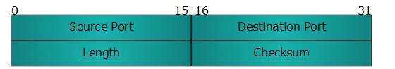
UDP header contains four main parameters:
Source Port - This 16 bits information is used to identify the source port of the packet.
Destination Port - This 16 bits information, is used identify application level service on destination machine.
Length - Length field specifies the entire length of UDP packet (including header). It is 16-bits field and minimum value is 8-byte, i.e. the size of UDP header itself.
Checksum - This field stores the checksum value generated by the sender before sending. IPv4 has this field as optional so when checksum field does not contain any value it is made 0 and all its bits are set to zero.
UDP application
Here are few applications where UDP is used to transmit data:
Domain Name Services
Simple Network Management Protocol
Trivial File Transfer Protocol
Routing Information Protocol
Kerberos
Application Layer Introduction
Application layer is the top most layer in OSI and TCP/IP layered model. This layer exists in both layered Models because of its significance, of interacting with user and user applications. This layer is for applications which are involved in communication system.
A user may or may not directly interacts with the applications. Application layer is where the actual communication is initiated and reflects. Because this layer is on the top of the layer stack, it does not serve any other layers. Application layer takes the help of Transport and all layers below it to communicate or transfer its data to the remote host.
When an application layer protocol wants to communicate with its peer application layer protocol on remote host, it hands over the data or information to the Transport layer. The transport layer does the rest with the help of all the layers below it.
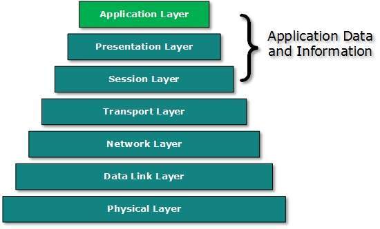
There’is an ambiguity in understanding Application Layer and its protocol. Not every user application can be put into Application Layer. except those applications which interact with the communication system. For example, designing software or text-editor cannot be considered as application layer programs.
On the other hand, when we use a Web Browser, which is actually using Hyper Text Transfer Protocol (HTTP) to interact with the network. HTTP is Application Layer protocol.
Another example is File Transfer Protocol, which helps a user to transfer text based or binary files across the network. A user can use this protocol in either GUI based software like FileZilla or CuteFTP and the same user can use FTP in Command Line mode.
Hence, irrespective of which software you use, it is the protocol which is considered at Application Layer used by that software. DNS is a protocol which helps user application protocols such as HTTP to accomplish its work.
Client Server Model
Two remote application processes can communicate mainly in two different fashions:
Peer-to-peer: Both remote processes are executing at same level and they exchange data using some shared resource.
Client-Server: One remote process acts as a Client and requests some resource from another application process acting as Server.
In client-server model, any process can act as Server or Client. It is not the type of machine, size of the machine, or its computing power which makes it server; it is the ability of serving request that makes a machine a server.
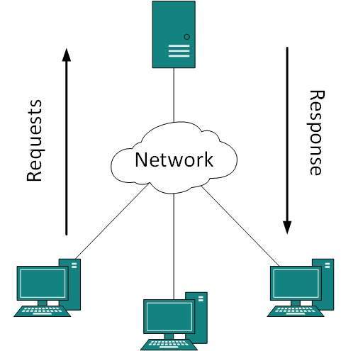
A system can act as Server and Client simultaneously. That is, one process is acting as Server and another is acting as a client. This may also happen that both client and server processes reside on the same machine.
Communication
Two processes in client-server model can interact in various ways:
Sockets
Remote Procedure Calls (RPC)
Sockets
In this paradigm, the process acting as Server opens a socket using a well-known (or known by client) port and waits until some client request comes. The second process acting as a Client also opens a socket but instead of waiting for an incoming request, the client processes ‘requests first’.
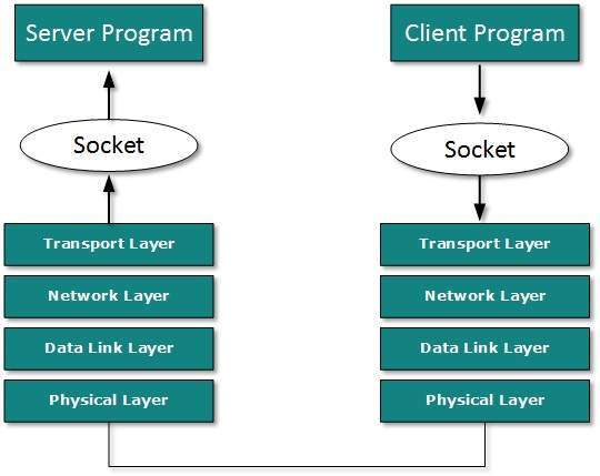
When the request is reached to server, it is served. It can either be an information sharing or resource request.
Remote Procedure Call
This is a mechanism where one process interacts with another by means of procedure calls. One process (client) calls the procedure lying on remote host. The process on remote host is said to be Server. Both processes are allocated stubs. This communication happens in the following way:
The client process calls the client stub. It passes all the parameters pertaining to program local to it.
All parameters are then packed (marshalled) and a system call is made to send them to other side of the network.
Kernel sends the data over the network and the other end receives it.
The remote host passes data to the server stub where it is unmarshalled.
The parameters are passed to the procedure and the procedure is then executed.
The result is sent back to the client in the same manner.
Application Protocols
There are several protocols which work for users in Application Layer. Application layer protocols can be broadly divided into two categories:
Protocols which are used by users.For email for example, eMail.
Protocols which help and support protocols used by users.For example DNS.
Few of Application layer protocols are described below:
Domain Name System
The Domain Name System (DNS) works on Client Server model. It uses UDP protocol for transport layer communication. DNS uses hierarchical domain based naming scheme. The DNS server is configured with Fully Qualified Domain Names (FQDN) and email addresses mapped with their respective Internet Protocol addresses.
A DNS server is requested with FQDN and it responds back with the IP address mapped with it. DNS uses UDP port 53.
Simple Mail Transfer Protocol
The Simple Mail Transfer Protocol (SMTP) is used to transfer electronic mail from one user to another. This task is done by means of email client software (User Agents) the user is using. User Agents help the user to type and format the email and store it until internet is available. When an email is submitted to send, the sending process is handled by Message Transfer Agent which is normally comes inbuilt in email client software.
Message Transfer Agent uses SMTP to forward the email to another Message Transfer Agent (Server side). While SMTP is used by end user to only send the emails, the Servers normally use SMTP to send as well as receive emails. SMTP uses TCP port number 25 and 587.
Client software uses Internet Message Access Protocol (IMAP) or POP protocols to receive emails.
File Transfer Protocol
The File Transfer Protocol (FTP) is the most widely used protocol for file transfer over the network. FTP uses TCP/IP for communication and it works on TCP port 21. FTP works on Client/Server Model where a client requests file from Server and server sends requested resource back to the client.
FTP uses out-of-band controlling i.e. FTP uses TCP port 20 for exchanging controlling information and the actual data is sent over TCP port 21.
The client requests the server for a file. When the server receives a request for a file, it opens a TCP connection for the client and transfers the file. After the transfer is complete, the server closes the connection. For a second file, client requests again and the server reopens a new TCP connection.
Post Office Protocol (POP)
The Post Office Protocol version 3 (POP 3) is a simple mail retrieval protocol used by User Agents (client email software) to retrieve mails from mail server.
When a client needs to retrieve mails from server, it opens a connection with the server on TCP port 110. User can then access his mails and download them to the local computer. POP3 works in two modes. The most common mode the delete mode, is to delete the emails from remote server after they are downloaded to local machines. The second mode, the keep mode, does not delete the email from mail server and gives the user an option to access mails later on mail server.
Hyper Text Transfer Protocol (HTTP)
The Hyper Text Transfer Protocol (HTTP) is the foundation of World Wide Web. Hypertext is well organized documentation system which uses hyperlinks to link the pages in the text documents. HTTP works on client server model. When a user wants to access any HTTP page on the internet, the client machine at user end initiates a TCP connection to server on port 80. When the server accepts the client request, the client is authorized to access web pages.
To access the web pages, a client normally uses web browsers, who are responsible for initiating, maintaining, and closing TCP connections. HTTP is a stateless protocol, which means the Server maintains no information about earlier requests by clients.
HTTP versions
HTTP 1.0 uses non persistent HTTP. At most one object can be sent over a single TCP connection.
HTTP 1.1 uses persistent HTTP. In this version, multiple objects can be sent over a single TCP connection.
Network Services
Computer systems and computerized systems help human beings to work efficiently and explore the unthinkable. When these devices are connected together to form a network, the capabilities are enhanced multiple-times. Some basic services computer network can offer are.
Directory Services
These services are mapping between name and its value, which can be variable value or fixed. This software system helps to store the information, organize it, and provides various means of accessing it.
Accounting
In an organization, a number of users have their user names and passwords mapped to them. Directory Services provide means of storing this information in cryptic form and make available when requested.
Authentication and Authorization
User credentials are checked to authenticate a user at the time of login and/or periodically. User accounts can be set into hierarchical structure and their access to resources can be controlled using authorization schemes.
Domain Name Services
DNS is widely used and one of the essential services on which internet works. This system maps IP addresses to domain names, which are easier to remember and recall than IP addresses. Because network operates with the help of IP addresses and humans tend to remember website names, the DNS provides website’s IP address which is mapped to its name from the back-end on the request of a website name from the user.
File Services
File services include sharing and transferring files over the network.
File Sharing
One of the reason which gave birth to networking was file sharing. File sharing enables its users to share their data with other users. User can upload the file to a specific server, which is accessible by all intended users. As an alternative, user can make its file shared on its own computer and provides access to intended users.
File Transfer
This is an activity to copy or move file from one computer to another computer or to multiple computers, with help of underlying network. Network enables its user to locate other users in the network and transfers files.
Communication Services
Email
Electronic mail is a communication method and something a computer user cannot work without. This is the basis of today’s internet features. Email system has one or more email servers. All its users are provided with unique IDs. When a user sends email to other user, it is actually transferred between users with help of email server.
Social Networking
Recent technologies have made technical life social. The computer savvy peoples, can find other known peoples or friends, can connect with them, and can share thoughts, pictures, and videos.
Internet Chat
Internet chat provides instant text transfer services between two hosts. Two or more people can communicate with each other using text based Internet Relay Chat services. These days, voice chat and video chat are very common.
Discussion Boards
Discussion boards provide a mechanism to connect multiple peoples with same interests.It enables the users to put queries, questions, suggestions etc. which can be seen by all other users. Other may respond as well.
Remote Access
This service enables user to access the data residing on the remote computer. This feature is known as Remote desktop. This can be done via some remote device, e.g. mobile phone or home computer.
Application Services
These are nothing but providing network based services to the users such as web services, database managing, and resource sharing.
Resource Sharing
To use resources efficiently and economically, network provides a mean to share them. This may include Servers, Printers, and Storage Media etc.
Databases
This application service is one of the most important services. It stores data and information, processes it, and enables the users to retrieve it efficiently by using queries. Databases help organizations to make decisions based on statistics.
Web Services
World Wide Web has become the synonym for internet.It is used to connect to the internet, and access files and information services provided by the internet servers.
To Continue Learning Please Login