
 Data Structure
 Networking
 RDBMS
RDBMS Operating System
 Java
Java MS Excel
 iOS
iOS HTML
HTML CSS
CSS Android
 Python
 C Programming
 C++
C++ C#
C# MongoDB
 MySQL
MySQL Javascript
 PHP
PHP
- Selected Reading
- UPSC IAS Exams Notes
- Developer's Best Practices
- Questions and Answers
- Effective Resume Writing
- HR Interview Questions
- Computer Glossary
- Who is Who
What is Microsequencer Operations?
A microsequencer is also designed as a finite state machine. Consider the generic microsequencer shown in the figure. The register stores a value that corresponds to one state in the CPU’s state diagram. It serves as the address that is input to the microcode memory. This memory outputs a microinstruction, the contents of the memory location for that address.
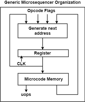
The microinstruction consists of a several-bit field, which can be broken into two groups. The first group is the microoperations. These signals are output from the microsequencer to the rest of the CPU. The second group of bits of the microinstruction is used to generate the next address to be stored in the register (the sequence part of the microsequencer).
These bits along with the instructions opcode and flag values are input to combinatorial logic that generates the address of the next microinstruction. This is similar to creating a transition from one state to another in the state diagram. The microsequencer makes this transition based on its current state and the value of its inputs.
The microsequencer may follow any sequence of addresses the designer wishes to use, but there are only a few standard ways of generating these addresses. The generate next address block of the microsequencer typically generates all possible next addresses and then selects the correct next address to pass along to the register.
One possible value of the next address is the next address in microcode memory, the current address plus 1. A typical high-level language computer program has blocks of statements that are executed sequentially. Microcode routines also usually occupy sequential locations in microcode memory. This improves readability and makes debugging the microprogram easier. In many CPUs, the microinstruction that comprises the fetch routine and each individual execute routine are stored in consecutive locations.
A microsequencer typically uses a parallel adder to generate the value of the current address plus 1 as a possible next address. For instance, at the end of every executes routine, the microsequencer must jump back to the beginning of the fetch routine. Jumps can also be used to make more efficient use of microcode memory.
Every microsequencer must be able to access the correct execute routine. A microsequencer uses mapping logic to perform this function. The opcode of the fetched instruction is input to the mapping hardware, which converts or maps, this opcode to the address of the first microinstruction of the instructions execute routine.
By loading this address into its register, the microsequencer branches to the correct execute routine. The mapping hardware is used only once in the CPU at the end of the fetch cycle.
When several instructions must perform the same sequence of microoperations as part of their execution, the sequence can be implemented as a micro-subroutine. When a micro-subroutine is called, the address is specified by the microcode memory as an absolute address, just as for a jump. The return address, the current address plus 1, is stored in a microsubroutine register or hardware stack.

565 Views
