- Home
- Brief Overview of IoT
- Introduction to ESP32
- Installing the ESP32 Board in Arduino IDE
- Setting up RTOS for dual-core and multi-threaded operation
- Interfacing ESP32 with MPU6050
- Interfacing ESP32 with Analog sensors
- ESP32 Preferences
- ESP32 SPIFFS storage (A mini-SD Card in the chip itself)
- Interfacing OLED Display with ESP32
- WiFi on ESP32
- Transmitting data over WiFi using HTTP
- Transmitting data over WiFi using HTTPS
- Transmitting data over WiFi using MQTT
- Transmitting data over Bluetooth
- Getting current time using NTP Client
- Performing the (OTA) update of ESP32 firmware
- Applications of ESP32
- Next steps for you as a developer
- ESP32 for IoT Useful Resources
- Quick Guide
- Useful Resources
- Discussion
Introduction to ESP32
ESP32 is the SoC (System on Chip) microcontroller which has gained massive popularity recently. Whether the popularity of ESP32 grew because of the growth of IoT or whether IoT grew because of the introduction of ESP32 is debatable. If you know 10 people who have been part of the firmware development for any IoT device, chances are that 7−8 of them would have worked on ESP32 at some point. So what is the hype all about? Why has ESP32 become so popular so quickly? Let's find out.
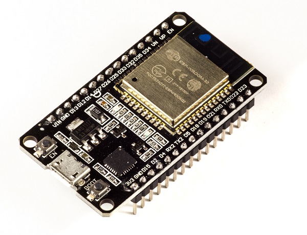
Before we delve into the actual reasons for the popularity of ESP32, let's take a look at some of its important specifications. The specs listed below belong to the ESP32 WROOM 32 variant.−
Integrated Crystal− 40 MHz
Module Interfaces− UART, SPI, I2C, PWM, ADC, DAC, GPIO, pulse counter, capacitive touch sensor
Integrated SPI flash− 4 MB
ROM− 448 KB (for booting and core functions)
SRAM− 520 KB
Integrated Connectivity Protocols− WiFi, Bluetooth, BLE
On−chip sensor− Hall sensor
Operating temperature range− −40 − 85 degrees Celsius
Operating Voltage− 3.3V
Operating Current− 80 mA (average)
With the above specifications in front of you, it is very easy to decipher the reasons for ESP32's popularity. Consider the requirements an IoT device would have from its microcontroller (μC). If you've gone through the previous chapter, you'd have realized that the major operational blocks of any IoT device are sensing, processing, storage, and transmitting. Therefore, to begin with, the μC should be able to interface with a variety of sensors. It should support all the common communication protocols required for sensor interface: UART, I2C, SPI. It should have ADC and pulse counting capabilities. ESP32 fulfills all of these requirements. On top of that, it also can interface with capacitive touch sensors. Therefore, most common sensors can interface seamlessly with ESP32.
Secondly, the μC should be able to perform basic processing of the incoming sensor data, sometimes at high speeds, and have sufficient memory to store the data. ESP32 has a max operating frequency of 40 MHz, which is sufficiently high. It has two cores, allowing parallel processing, which is a further add-on. Finally, its 520 KB SRAM is sufficiently large for processing a large array of data onboard. Many popular processes and transforms, like FFT, peak detection, RMS calculation, etc. can be performed onboard ESP32. On the storage front, ESP32 goes a step ahead of the conventional microcontrollers and provides a file system within the flash. Out of the 4 MB of onboard flash, by default, 1.5 MB is reserved as SPIFFS (SPI Flash File System). Think of it as a mini−SD Card that lies within the chip itself. You can not only store data, but also text files, images, HTML and CSS files, and a lot more within SPIFFS. People have displayed beautiful Webpages on WiFi servers created using ESP32, by storing HTML files within SPIFFS.
Finally, for transmitting data, ESP32 has integrated WiFi and Bluetooth stacks, which have proven to be a game-changer. No need to connect a separate module (like a GSM module or an LTE module) for testing cloud communication. Just have the ESP32 board and a running WiFi, and you can get started. ESP32 allows you to use WiFi in Access Point as well as Station Mode. While it supports TCP/IP, HTTP, MQTT, and other traditional communication protocols, it also supports HTTPS. Yep, you heard that right. It has a crypto−core or a crypto-accelerator, a dedicated piece of hardware whose job is to accelerate the encryption process. So you cannot only communicate with your web server, you can do so securely. BLE support is also critical for several applications. Of course, you can interface LTE or GSM or LoRa modules with ESP32. Therefore, on the 'transmitting data' front as well, ESP32 exceeds expectations.
With so many features, ESP32 would be costing a fortune, right? That's the best part. ESP32 dev modules cost in the ballpark of ₹ 500. Not only that, the chip dimensions are quite small (25 mm x 18 mm, including the antenna area), allowing its use in devices requiring a very small form factor.
Finally, ESP32 can be programmed using the Arduino IDE, making the learning curve much less steep. Isn't that great? Are you excited to get your hands dirty with ESP32? Then let's start by installing the ESP32 board in the Arduino IDE in the next chapter. See you there.
