- Electrical Machines - Home
- Basic Concepts
- Electromechanical Energy Conversion
- Energy Stored in Magnetic Field
- Singly-Excited and Doubly Excited Systems
- Rotating Electrical Machines
- Electrical Machines Types
- Faraday’s Laws of Electromagnetic Induction
- Concept of Induced EMF
- Fleming's Left Hand and Right Hand Rules
- Transformers
- Electrical Transformer
- Construction of Transformer
- EMF Equation of Transformer
- Turns Ratio and Voltage Transformation Ratio
- Ideal Transformer
- Practical Transformer
- Ideal and Practical Transformers
- Transformer on DC
- Losses in a Transformer
- Efficiency of Transformer
- 3-Phase Transformer
- Types of Transformers
- More on Transformers
- Transformer Working Principle
- Single-Phase Transformer Working Principle
- 3-Phase Transformer Principle
- 3-Phase Induction Motor Torque-Slip
- 3-Phase Induction Motor Torque-Speed
- 3-Phase Transformer Harmonics
- Double-Star Connection (3-6 Phase)
- Double-delta Connection (3-6 Phase)
- Transformer Ratios
- Voltage Regulation
- Delta-Star Connection (3-Phase)
- Star-Delta Connection (3-Phase)
- Autotransformer Conversion
- Back-to-back Test (Sumpner's Test)
- Transformer Voltage Drop
- Autotransformer Output
- Open and Short Circuit Test
- 3-Phase Autotransformer
- Star-Star Connection
- 6-Phase Diametrical Connections
- Circuit Test (Three-Winding)
- Potential Transformer
- Transformers Parallel Operation
- Open Delta (V-V) Connection
- Autotransformer
- Current Transformer
- No-Load Current Wave
- Transformer Inrush Current
- Transformer Vector Groups
- 3 to 12-Phase Transformers
- Scott-T Transformer Connection
- Transformer kVA Rating
- Three-Winding Transformer
- Delta-Delta Connection Transformer
- Transformer DC Supply Issue
- Equivalent Circuit Transformer
- Simplified Equivalent Circuit of Transformer
- Transformer No-Load Condition
- Transformer Load Condition
- OTI WTI Transformer
- CVT Transformer
- Isolation vs Regular Transformer
- Dry vs Oil-Filled
- DC Machines
- Construction of DC Machines
- Types of DC Machines
- Working Principle of DC Generator
- EMF Equation of DC Generator
- Derivation of EMF Equation DC Generator
- Types of DC Generators
- Working Principle of DC Motor
- Back EMF in DC Motor
- Types of DC Motors
- Losses in DC Machines
- Applications of DC Machines
- More on DC Machines
- DC Generator
- DC Generator Armature Reaction
- DC Generator Commutator Action
- Stepper vs DC Motors
- DC Shunt Generators Critical Resistance
- DC Machines Commutation
- DC Motor Characteristics
- Synchronous Generator Working Principle
- DC Generator Characteristics
- DC Generator Demagnetizing & Cross-Magnetizing
- DC Motor Voltage & Power Equations
- DC Generator Efficiency
- Electric Breaking of DC Motors
- DC Motor Efficiency
- Four Quadrant Operation of DC Motors
- Open Circuit Characteristics of DC Generators
- Voltage Build-Up in Self-Excited DC Generators
- Types of Armature Winding in DC Machines
- Torque in DC Motors
- Swinburne’s Test of DC Machine
- Speed Control of DC Shunt Motor
- Speed Control of DC Series Motor
- DC Motor of Speed Regulation
- Hopkinson's Test
- Permanent Magnet DC Motor
- Permanent Magnet Stepper Motor
- DC Servo Motor Theory
- DC Series vs Shunt Motor
- BLDC Motor vs PMSM Motor
- Induction Motors
- Introduction to Induction Motor
- Single-Phase Induction Motor
- 3-Phase Induction Motor
- Construction of 3-Phase Induction Motor
- 3-Phase Induction Motor on Load
- Characteristics of 3-Phase Induction Motor
- Speed Regulation and Speed Control
- Methods of Starting 3-Phase Induction Motors
- More on Induction Motors
- 3-Phase Induction Motor Working Principle
- 3-Phase Induction Motor Rotor Parameters
- Double Cage Induction Motor Equivalent Circuit
- Induction Motor Equivalent Circuit Models
- Slip Ring vs Squirrel Cage Induction Motors
- Single-Cage vs Double-Cage Induction Motor
- Induction Motor Equivalent Circuits
- Induction Motor Crawling & Cogging
- Induction Motor Blocked Rotor Test
- Induction Motor Circle Diagram
- 3-Phase Induction Motors Applications
- 3-Phase Induction Motors Torque Ratios
- Induction Motors Power Flow Diagram & Losses
- Determining Induction Motor Efficiency
- Induction Motor Speed Control by Pole-Amplitude Modulation
- Induction Motor Inverted or Rotor Fed
- High Torque Cage Motors
- Double-Cage Induction Motor Torque-Slip Characteristics
- 3-Phase Induction Motors Starting Torque
- 3-phase Induction Motor - Rotor Resistance Starter
- 3-phase Induction Motor Running Torque
- 3-Phase Induction Motor - Rotating Magnetic Field
- Isolated Induction Generator
- Capacitor-Start Induction Motor
- Capacitor-Start Capacitor-Run Induction Motor
- Winding EMFs in 3-Phase Induction Motors
- Split-Phase Induction Motor
- Shaded Pole Induction Motor
- Repulsion-Start Induction-Run Motor
- Repulsion Induction Motor
- PSC Induction Motor
- Single-Phase Induction Motor Performance Analysis
- Linear Induction Motor
- Single-Phase Induction Motor Testing
- 3-Phase Induction Motor Fault Types
- Synchronous Machines
- Introduction to 3-Phase Synchronous Machines
- Construction of Synchronous Machine
- Working of 3-Phase Alternator
- Armature Reaction in Synchronous Machines
- Output Power of 3-Phase Alternator
- Losses and Efficiency of an Alternator
- Losses and Efficiency of 3-Phase Alternator
- Working of 3-Phase Synchronous Motor
- Equivalent Circuit and Power Factor of Synchronous Motor
- Power Developed by Synchronous Motor
- More on Synchronous Machines
- AC Motor Types
- Induction Generator (Asynchronous Generator)
- Synchronous Speed Slip of 3-Phase Induction Motor
- Armature Reaction in Alternator at Leading Power Factor
- Armature Reaction in Alternator at Lagging Power Factor
- Stationary Armature vs Rotating Field Alternator Advantages
- Synchronous Impedance Method for Voltage Regulation
- Saturated & Unsaturated Synchronous Reactance
- Synchronous Reactance & Impedance
- Significance of Short Circuit Ratio in Alternator
- Hunting Effect Alternator
- Hydrogen Cooling in Synchronous Generators
- Excitation System of Synchronous Machine
- Equivalent Circuit Phasor Diagram of Synchronous Generator
- EMF Equation of Synchronous Generator
- Cooling Methods for Synchronous Generators
- Assumptions in Synchronous Impedance Method
- Armature Reaction at Unity Power Factor
- Voltage Regulation of Alternator
- Synchronous Generator with Infinite Bus Operation
- Zero Power Factor of Synchronous Generator
- Short Circuit Ratio Calculation of Synchronous Machines
- Speed-Frequency Relationship in Alternator
- Pitch Factor in Alternator
- Max Reactive Power in Synchronous Generators
- Power Flow Equations for Synchronous Generator
- Potier Triangle for Voltage Regulation in Alternators
- Parallel Operation of Alternators
- Load Sharing in Parallel Alternators
- Slip Test on Synchronous Machine
- Constant Flux Linkage Theorem
- Blondel's Two Reaction Theory
- Synchronous Machine Oscillations
- Ampere Turn Method for Voltage Regulation
- Salient Pole Synchronous Machine Theory
- Synchronization by Synchroscope
- Synchronization by Synchronizing Lamp Method
- Sudden Short Circuit in 3-Phase Alternator
- Short Circuit Transient in Synchronous Machines
- Power-Angle of Salient Pole Machines
- Prime-Mover Governor Characteristics
- Power Input of Synchronous Generator
- Power Output of Synchronous Generator
- Power Developed by Salient Pole Motor
- Phasor Diagrams of Cylindrical Rotor Moto
- Synchronous Motor Excitation Voltage Determination
- Hunting Synchronous Motor
- Self-Starting Synchronous Motor
- Unidirectional Torque Production in Synchronous Motor
- Effect of Load Change on Synchronous Motor
- Field Excitation Effect on Synchronous Motor
- Output Power of Synchronous Motor
- Input Power of Synchronous Motor
- V Curves & Inverted V Curves of Synchronous Motor
- Torque in Synchronous Motor
- Construction of 3-Phase Synchronous Motor
- Synchronous Motor
- Synchronous Condenser
- Power Flow in Synchronous Motor
- Types of Faults in Alternator
- Miscellaneous Topics
- Electrical Generator
- Determining Electric Motor Load
- Solid State Motor Starters
- Characteristics of Single-Phase Motor
- Types of AC Generators
- Three-Point Starter
- Four-Point Starter
- Ward Leonard Speed Control Method
- Pole Changing Method
- Stator Voltage Control Method
- DOL Starter
- Star-Delta Starter
- Hysteresis Motor
- 2-Phase & 3-Phase AC Servo Motors
- Repulsion Motor
- Reluctance Motor
- Stepper Motor
- PCB Motor
- Single-Stack Variable Reluctance Stepper Motor
- Schrage Motor
- Hybrid Schrage Motor
- Multi-Stack Variable Reluctance Stepper Motor
- Universal Motor
- Step Angle in Stepper Motor
- Stepper Motor Torque-Pulse Rate Characteristics
- Distribution Factor
- Electrical Machines Basic Terms
- Synchronizing Torque Coefficient
- Synchronizing Power Coefficient
- Metadyne
- Motor Soft Starter
- CVT vs PT
- Metering CT vs Protection CT
- Stator and Rotor in Electrical Machines
- Electric Motor Winding
- Electric Motor
- Useful Resources
- Quick Guide
- Resources
- Discussion
Construction and Working Principle of Synchronous Generator
A synchronous generator is a synchronous machine which converts mechanical power into AC electric power through the process of electromagnetic induction.
Synchronous generators are also referred to as alternators or AC generators. The term "alternator" is used since it produces AC power. It is called synchronous generator because it must be driven at synchronous speed to produce AC power of the desired frequency.
A synchronous generator can be either single-phase or poly-phase (generally 3phase).
Construction of Synchronous Generator or Alternator
As alternator consists of two main parts viz.
- Stator − The stator is the stationary part of the alternator. It carries the armature winding in which the voltage is generated. The output of the alternator is taken form the stator.
- Rotor − The rotor is the rotating part of the alternator. The rotor produces the main field flux.
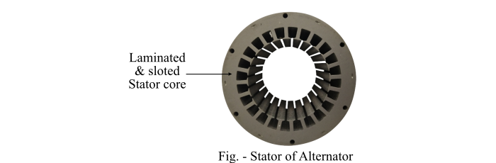
Stator Construction of Alternator
The stator of the alternator includes several parts, viz. the frame, stator core, stator or armature windings, and cooling arrangement.
- The stator frame may be made up of cast iron for small-size machines and of welded steel for large-size machines.
- The stator core is assembled with high-grade silicon content steel laminations. These silicon steel laminations reduce the hysteresis and eddy-current losses in the stator core.
- The slots are cut on the inner periphery of the stator core. A 3-phase armature winding is put in these slots.
- The armature winding of the alternator is star connected. The winding of each phase is distributed over several slots. When current flows through the distributed armature winding, it produces an essential sinusoidal space distribution of EMF.
Rotor Construction of Alternator
The rotor of the alternator carries the field winding which is supplied with direct current through two slip rings by a separate DC source (also called exciter). The exciter is generally a small DC shunt generator mounted on the shaft of the alternator.
For the alternator, there are two types of rotor constructions are used viz. the salient-pole type and the cylindrical rotor type.
Salient Pole Rotor
The term salient means projecting. Hence, a salient pole rotor consists of poles projecting out from the surface of the rotor core. This whole arrangement is fixed to the shaft of the alternator as shown in the figure. The individual field pole windings are connected in series such that when the field winding is energised by the DC exciter, the adjacent poles have opposite polarities.

The salient pole type rotor is used in the low and medium speed (from 120 to 400 RPM) alternators such as those driven by the diesel engines or water turbines because of the following reasons −
- The construction of salient pole type rotor cannot be made b enough to withstand the mechanical stresses to which they may be subjected at higher speed.
- If the salient field pole type rotor is driven at high speed, then it would cause windage loss and would tend to produce noise.
Low speed rotors of the alternators possess a large diameter to provide the necessary space for the poles. As a result, the salient pole type rotors have large diameter and short axial length.
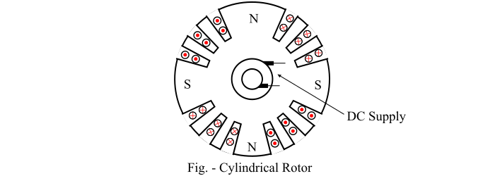
Cylindrical Rotor
The cylindrical rotors are made from solid forgings of high-grade nickel-chrome-molybdenum steel.
- The construction of the cylindrical rotor is such that there are no-physical poles to be seen as in the salient pole rotor.
- In about two-third of the outer periphery of the cylindrical rotor, slots are cut at regular intervals and parallel to the rotor shaft.
- The field windings are placed in these slots and is excited by DC supply. The field winding is of distributed type.
- The unslotted portion of the rotor forms the pole faces.
- It is clear from the figure of the cylindrical rotor that the poles formed are non-salient, i.e., they do not project out from the rotor surface.
The cylindrical type rotor construction is used in the high-speed (1500 to 3000 RPM) alternators such as those driven by steam turbines because of the following reasons −
- The cylindrical type rotor construction provides a greater mechanical strength and permits more accurate dynamic balancing.
- It gives noiseless operation at high speeds because of the uniform air gap.
- The flux distribution around the periphery of the rotor is nearly a sine wave and hence a better EMF waveform is obtained.
A cylindrical rotor alternator has a comparatively small diameter and long axial length. The cylindrical rotor alternators are called turbo-alternators or turbo-generators. The alternator with cylindrical rotor have always horizontal configuration installation.
Working Principle and Operation of Alternator
An alternator or synchronous generator works on the principle of electromagnetic induction, i.e., when the flux linking a conductor changes, an EMF is induced in the conductor. When the armature winding of alternator subjected to the rotating magnetic field, the voltage will be generated in the armature winding.
When the rotor field winding of the alternator is energised from the DC exciter, the alternate N and S poles are developed on the rotor. When the rotor is rotated in the anticlockwise direction by a prime mover, the armature conductors placed on the stator are cut by the magnetic field of the rotor poles. As a result, the EMF is induced in the armature conductors due to electromagnetic induction. This induced EMF is alternating one because the N and S poles of the rotor pass the armature conductors alternatively.
The direction of the generated EMF can be determined by the Fleming’s right rule and the frequency of it is given by,
$$\mathrm{f \:=\:\frac{N_{s}P}{120}}$$
Where,
- Ns is the synchronous speed in RP
- P is the number of rotor poles.
The magnitude of the generated voltage depends upon the speed of rotation of the rotor and the DC field excitation current. For the balanced condition, the generated voltage in each phase of the winding is the same but differ in phase by 120° electrical.
