
Article Categories
- All Categories
-
 Data Structure
-
 Networking
-
 RDBMS
RDBMS
-
 Operating System
-
 Java
Java
-
 MS Excel
-
 iOS
iOS
-
 HTML
HTML
-
 CSS
CSS
-
 Android
-
 Python
-
 C Programming
-
 C++
C++
-
 C#
C#
-
 MongoDB
-
 MySQL
MySQL
-
 Javascript
-
 PHP
PHP
-
 Economics & Finance
Electrodynamometer Wattmeter – Construction and Working Principle
An electrodynamometer or simply Dynamometer wattmeter is an instrument that is universally used for the measurement of DC as well as AC electric power.
It works on the principle of dynamometer i.e. a mechanical force acts between two current carrying conductors.
Construction of Electrodynamometer
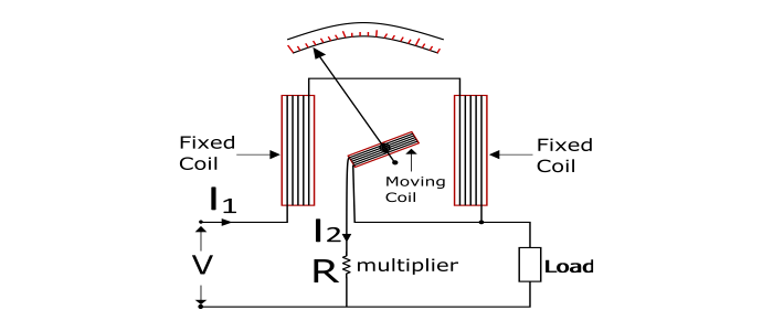
The electrodynamometer wattmeter has a fixed coil divided into two parts and is connected in series with the load and caries the load current (I1). The moving coil is connected across the load through a series multiplier resistance (R) and carries a current (I2) proportional to the load voltage. The fixed coil is called as Current Coil and the moving coil is called as Potential Coil. The controlling torque is provided by two spiral springs. Air friction damping is provided in electrodynamometer wattmeter. A pointer is attached with the moving coil.
Working Principle of Electrodynamometer
When electrodynamometer wattmeter is connected in the circuit to measure the electric power. The current coil carries the load current and the potential coil carries a current proportional to the load voltage. Because of the current in the two coils, a mechanical force acts between them due to which the moving coil (potential coil) moves and hence the pointer attached to it. The pointer comes to rest at a position where the deflecting torque and controlling torque become equal.
When the current is reversed in the circuit, the reversal of current takes place in both the current coil and potential coil so that the direction of the deflecting torque remains unchanged. Hence, the electrodynamometer wattmeter can be used for the measurement of DC as well as AC power.

Deflecting Torque
The deflecting of electrodynamometer wattmeter is proportional to the load power in DC as well as AC circuit.
DC circuit – When the wattmeter is connected in DC circuit for power measurement, the power taken by the load is VI1.
$$Deflecting\:Torque(\tau_{d})\varpropto\:l_{1}l_{2}$$
Since the current I2 is proportional to load voltage V. Thus,
$$Deflecting\:Torque(\tau_{d})\varpropto\:l_{1}V\varpropto\:Load\:Power$$
AC Circuit – When the wattmeter is connected in an AC circuit to measure the load power. Consider at any instant, current through the load is i and voltage across the load is v and the power factor of the load is supposed to be cos φ lagging.
$$\nu=V_{m}\sin\theta$$
$$i=I_{m}\sin(\theta-\varphi)$$
$$Instantaneous\:deflecting\:torque\varpropto\:\nu\:i$$
Due to inertia of moving system, the pointer cannot follow the rapid changes in the instantaneous power. Hence the wattmeter indicates the average power.
$$\therefore\:Average\:Deflecting\:torque(\tau_{d})\varpropto\:Average\:of\:vi\:over\:one\:cycle$$
$$\tau_{d}\varpropto\:\frac{1}{2\pi}\int_{0}^{2\pi}V_{m}I_{m}\sin\theta\sin(\theta-\varphi)d\theta\varpropto\:\frac{V_{m}I_{m}}{2}\cos\varphi\:\varpropto\:VI\cos\varphi$$
Where, V and I are RMS values
$$\tau_{d}\varpropto\:VI\cos\varphi\varpropto\:Load\:Power$$
Since the controlling torque in the wattmeter is provided by spring. Thus,
$$\tau_{c}\varpropto\:\theta$$
Under steady state condition,
$$\tau_{d}=\tau_{c}$$
Therefore,
$$\theta\varpropto\:Load\:Power$$
Hence the electrodynamometer wattmeter has uniform scale.
Advantages
Can be used for measurement of AC as well as DC power.
They have uniform scale.
By proper design, high accuracy can be obtained.
Disadvantages
The stray magnetic field may affect the wattmeter readings. In order to prevent this, the instrument should be enclosed in a soft-iron case.
At low power factors, serious errors may be caused by the inductance of potential coil.

51K+ Views
