 Data Structure
 Networking
 RDBMS
RDBMS Operating System
 Java
Java MS Excel
 iOS
iOS HTML
HTML CSS
CSS Android
 Python
 C Programming
 C++
C++ C#
C# MongoDB
 MySQL
MySQL Javascript
 PHP
PHP
- Selected Reading
- UPSC IAS Exams Notes
- Developer's Best Practices
- Questions and Answers
- Effective Resume Writing
- HR Interview Questions
- Computer Glossary
- Who is Who
Spanning Tree Protocol
Spanning Tree Protocol (STP) is a communication protocol operating at data link layer the OSI model to prevent bridge loops and the resulting broadcast storms. It creates a loop − free topology for Ethernet networks.
Working Principle
A bridge loop is created when there are more than one paths between two nodes in a given network. When a message is sent, particularly when a broadcast is done, the bridges repeatedly rebroadcast the same message flooding the network. Since a data link layer frame does not have a time-to-live field in the header, the broadcast frame may loop forever, thus swamping the channels.
Spanning tree protocol creates a spanning tree by disabling all links that form a loop or cycle in the network. This leaves exactly one active path between any two nodes of the network. So when a message is broadcast, there is no way that the same message can be received from an alternate path. The bridges that participate in spanning tree protocol are often called spanning tree bridges.
To construct a spanning tree, the bridges broadcast their configuration routes. Then they execute a distributed algorithm for finding out the minimal spanning tree in the network, i.e. the spanning tree with minimal cost. The links not included in this tree are disabled but not removed.
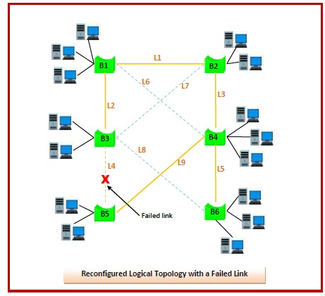
In case a particular active link fails, the algorithm is executed again to find the minimal spanning tree without the failed link. The communication continues through the newly formed spanning tree. When a failed link is restored, the algorithm is re-run including the newly restored link.
Example
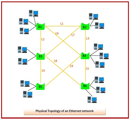
Let us consider a physical topology, as shown in the diagram, for an Ethernet network that comprises of six interconnected bridges. The bridges are named {B1, B2, B3, B4, B5, B6} and several nodes are connected to each bridge. The links between two bridges are named {L1, L2, L3, L4, L5, L6, L7, L8, L9}, where L1 connects B1 and B2, L2 connects B1 and B3 and so on. It is assumed that all links are of uniform costs.
From the diagram we can see that there are multiple paths from a bridge to any other bridge in the network, forming several bridge loops that makes the topology susceptible to broadcast storms.

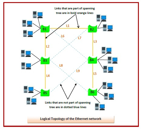
According to spanning tree protocol, links that form a cycle are disabled. Thus,we get a logical topology so that there is exactly one route between any two bridges. One possible logical topology is shown in the following diagram below containing links {L1, L2, L3, L4, L5} −

In the above logical configuration, if a situation arises such that link L4 fails. Then, the spanning tree is reconstituted leaving L4. A possible logical reconfiguration containing links {L1, L2, L3, L5, L9} is as follows −


