
Article Categories
- All Categories
-
 Data Structure
-
 Networking
-
 RDBMS
RDBMS
-
 Operating System
-
 Java
Java
-
 MS Excel
-
 iOS
iOS
-
 HTML
HTML
-
 CSS
CSS
-
 Android
-
 Python
-
 C Programming
-
 C++
C++
-
 C#
C#
-
 MongoDB
-
 MySQL
MySQL
-
 Javascript
-
 PHP
PHP
-
 Economics & Finance
Resistors in Parallel
When one end of each resistor is joined to a common point and the other end of each resistor is joined to another common point so that there are as many paths for current flow as the number of resistors, it is called as a parallel circuit.
The below circuit shows the connection of three resistors in parallel across a DC voltage source V. Let the circuit current be ? while the branch currents I1,I2 and I3 respectively. The voltage drop in each branch being same, so by Ohm’s law, we can write,
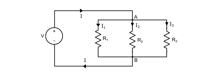
$$\mathrm{\mathit{V}=\mathit{I}_{1}\mathit{R}_{1}=\mathit{I}_{2}\mathit{R}_{2}=\mathit{I}_{3}\mathit{R}_{3}}$$
Also, by referring the circuit,
$$\mathrm{\mathit{I}=\mathit{I}_{1}+\mathit{I}_{2}+\mathit{I}_{3}}$$
$$\mathrm{\Rightarrow\frac{\mathit{V}}{\mathit{R}_{p}}=\frac{\mathit{V}}{\mathit{R}_{1}}+\frac{\mathit{V}}{\mathit{R}_{2}}+\frac{\mathit{V}}{\mathit{R}_{3}}}$$
Where, RP being the equivalent of three resistances in parallel. Therefore,
$$\mathrm{\frac{1}{\mathit{R}_{p}}=\frac{1}{\mathit{R}_{1}}+\frac{1}{\mathit{R}_{2}}+\frac{1}{\mathit{R}_{3}}}$$
The power loss in the above circuit is given by,
$$\mathrm{\mathit{P}_{p}=(\frac{\mathit{V}^{2}}{\mathit{R}_{1}}+\frac{\mathit{V}^{2}}{\mathit{R}_{2}}+\frac{\mathit{V}^{2}}{\mathit{R}_{3}})=(\mathit{I}_{1}^2\mathit{R}_{1}+\mathit{I}_{2}^2\mathit{R}_{2}+\mathit{I}_{3}^2\mathit{R}_{3})}$$
Therefore, the total power loss in the circuit is the sum of power loss in the individual resistances i.e.
$$\mathrm{\Rightarrow \mathit{P}_{p}=\mathit{P}_{1}+\mathit{P}_{2}+\mathit{P}_{3}}$$
Two Resistances in Parallel
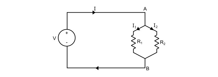
Here, the equivalent resistance of two branch circuit is
$$\mathrm{\frac{1}{\mathit{R}_{eq}}=\frac{1}{\mathit{R}_{1}}+\frac{1}{\mathit{R}_{2}}}$$
$$\mathrm{\Rightarrow\:\mathit{R}_{eq}=\frac{\mathit{R}_{1}\mathit{R}_{2}}{\mathit{R}_{1}+\mathit{R}_{2}}=\frac{Product\:of\:two\:resistances}{Sum\:of\:two\:resistances}}$$
Hence, in a parallel circuit of two resistors, the value of equivalent resistance is equal to the product divided by the sum of two resistors.
Also, for the two branch circuit,
$$\mathrm{\mathit{V}=\mathit{I}_{1}\mathit{R}_{1}=\mathit{I}_{2}\mathit{R}_{2}}$$
And,
$$\mathrm{\mathit{I}=\mathit{I}_{1}+\mathit{I}_{2}=\mathit{V}(\frac{1}{\mathit{R}_{1}}+\frac{1}{\mathit{R}_{2}})=\mathit{I}_{1}(\frac{\mathit{R}_{1}+\mathit{R}_{2}}{\mathit{R}_{2}})=\mathit{I}_{2}(\frac{\mathit{R}_{1}+\mathit{R}_{2}}{\mathit{R}_{1}})}$$
Hence,
$$\mathrm{\mathit{I}_{1}=\mathit{I}(\frac{\mathit{R}_{2}}{\mathit{R}_{1}+\mathit{R}_{2}})}$$
Similarly,
$$\mathrm{\mathit{I}_{2}=\mathit{I}(\frac{\mathit{R}_{1}}{\mathit{R}_{1}+R_{2}})}$$
Hence, in a parallel circuit of two resistors, the current in one resistor is the total current times the opposite resistor divided by the sum of two resistors.
Numerical Example - 1
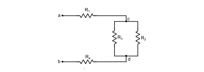
Find the equivalent resistance of the circuit shown below. Given, R1 = R4 = 10 Ω and R2 = RR3 = 5 Ω.
Solution
Given, R1 = R4 = 10 Ω and R2 = R3 = 5 Ω, then
Referring the circuit shown in the problem, we can write,
$$\mathrm{\Rightarrow\:\mathit{R}_{cd}=\frac{\mathit{R}_{2}\mathit{R}_{3}}{\mathit{R}_{2}+\mathit{R}_{3}}=\frac{5×5}{5+5}=2.5 Ω}$$
$$\mathrm{\Rightarrow\:\mathit{R}_{ab}=\mathit{R}_{1}+\mathit{R}_{cd}+\mathit{R}_{4}=10+2.5+10=22.5 Ω}$$
Thus, the equivalent resistance across the terminals a and b is equal to 22.5 Ω.
Numerical Example - 2
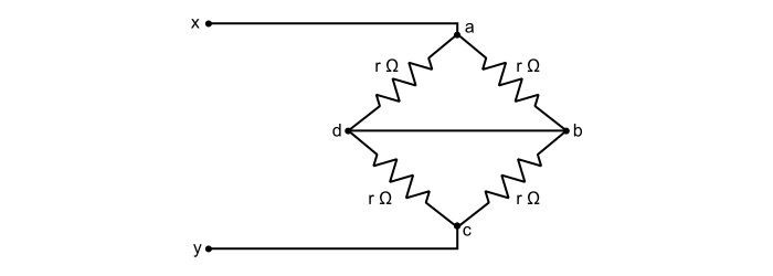
In the circuit shown below, determine the equivalent resistance across x-y terminals.
Solution
Rearranging the circuit as,
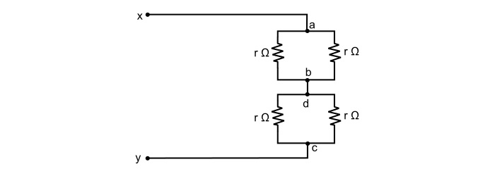
Here,
$$\mathrm{\mathit{R}_{ab}=\frac{r}{2}\:\:\:and\:\:\:\mathit{R}_{cd}=\frac{r}{2}}$$
$$\mathrm{\Rightarrow\:\mathit{R}_{xy}=\mathit{R}_{ab}+\mathit{R}_{cd}=\frac{r}{2}+\frac{r}{2}=r\:Ω}$$
Numerical Example - 3
Find the equivalent resistance of the circuit.
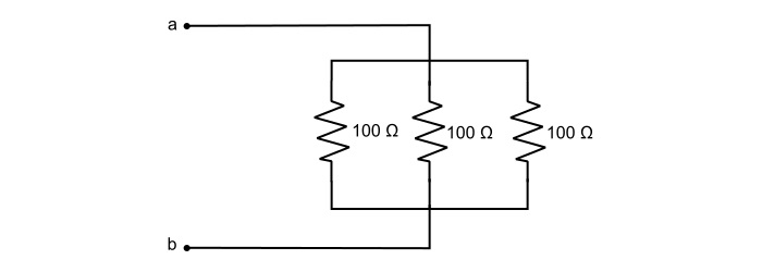
Solution
By referring the circuit,
$$\mathrm{\frac{1}{\mathit{R}_{ab}}=\frac{1}{100}+\frac{1}{100}+\frac{1}{100}=\frac{3}{100}}$$
$$\mathrm{\Rightarrow\:\mathit{R}_{ab}=\frac{3}{100}=33.33 Ω}$$

465 Views
