
Article Categories
- All Categories
-
 Data Structure
-
 Networking
-
 RDBMS
RDBMS
-
 Operating System
-
 Java
Java
-
 MS Excel
-
 iOS
iOS
-
 HTML
HTML
-
 CSS
CSS
-
 Android
-
 Python
-
 C Programming
-
 C++
C++
-
 C#
C#
-
 MongoDB
-
 MySQL
MySQL
-
 Javascript
-
 PHP
PHP
-
 Economics & Finance
Resistors in Series
The resistors are said to be connected in series, when they are joined end to end so that there is only one path for the current to flow.
Explanation
Let the three pure resistors R1, R2 and R3 be connected in series against a DC voltage source V as shown in the circuit.
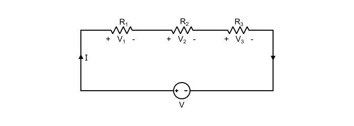
Referring the circuit it can be written that
$$\mathrm{\mathit{V}\:=\:\mathit{V}_{1}+\mathit{V}_{2}+\mathit{V}_{3}\:\:\:\:…(1)}$$
Where V1, V2 and V3 being the voltage drops against individual resistors.
Assuming I to be the total current in the circuit and R being the equivalent resistance of all the series resistors. Hence, the equation (1) can be written as
$$\mathrm{\mathit{IR}=\mathit{IR}_{1}+\mathit{IR}_{2}+\mathit{IR}_{3}}$$
$$\mathrm{\Rightarrow\:\mathit{R}=\mathit{R}_{1}+\mathit{R}_{2}+\mathit{R}_{3}\:\:\:\:…(2)}$$
Thus, the equation (2) proves that “the equivalent resistance of the resistors connected in series is the sum of individual resistances”.
The total power loss in series connected resistors is given by
$$\mathrm{\mathit{P}=\mathit{I}^{2}\mathit{R}_{1}+I^{2}\mathit{R}_{2}+I^{2}\mathit{R}_{3}}$$
$$\mathrm{\Rightarrow\:\mathit{P}=\mathit{I}^{2}(\mathit{R}_{1}+\mathit{R}_{2}+\mathit{R}_{3})=\mathit{I}(\mathit{V}_{1}+\mathit{V}_{2}+\mathit{V}_{3})}\:\:\:\:…(3)$$
Important Points about Series Connected Resistors
The total resistance of series connected resistors is equal to the sum of individual resistances.
The current in each resistor is the same.
The total or equivalent resistance of the series connected resistors is greater than the largest of the resistances.
The total power dissipated in the series connected resistors is equal to the sum of powers dissipated in individual resistances.
Numerical Example (1)
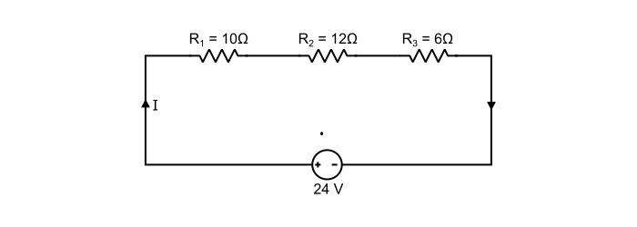
Determine the equivalent resistance of the circuit. Also, find the total circuit current and total power loss.
Solution
As, the resistors are connected in series, thus,
$$\mathrm{\mathit{R}_{eq}=\mathit{R}_{1}+\mathit{R}_{2}+\mathit{R}_{3}}$$
$$\mathrm{\Rightarrow\:\mathit{R}_{eq}=10+12+6=28 \:Ω}$$
Total circuit current is
$$\mathrm{\mathit{I}=\frac{\mathit{V}}{\mathit{R}_{eq}}=\frac{24}{28}=0.857\:A}$$
Total power loss in the circuit is
$$\mathrm{\mathit{P}=\mathit{I}^{2}\mathit{R}_{eq}=0.857^{2}×28=20.565 \:W}$$
Numerical Example -2
The filament of 200 Watt electric bulb is designed for use on a 110 V supply. What value of resistance is needed to be connected in series in order that the bulb can be operated from 230 V supply.
Solution
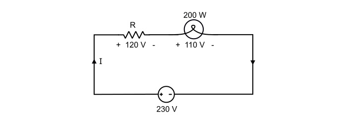
Referring the circuit,
$$\mathrm{Current\:rating\:of\:bulb,\mathit{I}=\frac{\mathit{P}}{\mathit{V}}=\frac{200}{110}=1.82 A}$$
If R ohms is the required value of resistor to be connected in series with the bulb, then,
$$\mathrm{Voltage\:drop\:across\:series\:resistor\:\mathit{V}_{R}=230−110=120\:V}$$
Therefore,
$$\mathrm{\mathit{R}=\frac{\mathit{V}_{R}}{\mathit{I}}=\frac{120}{1.82}=65.93\:Ω}$$

543 Views
