- Radar Systems - Home
- Radar Systems - Overview
- Radar Systems - Range Equation
- Performance Factors
- Radar Systems - Types of Radars
- Radar Systems - Pulse Radar
- Radar Systems - Doppler Effect
- Radar Systems - CW Radar
- Radar Systems - FMCW Radar
- Radar Systems - MTI Radar
- Delay Line Cancellers
- Radar Systems - Tracking Radar
- Antenna Parameters
- Radar Systems - Radar Antennas
- Matched Filter Receiver
- Radar Systems - Radar Displays
- Radar Systems - Duplexers
- Phased Array Antennas
Radar Systems - Phased Array Antennas
A single Antenna can radiate certain amount of power in a particular direction. Obviously, the amount of radiation power will be increased when we use group of Antennas together. The group of Antennas is called Antenna array.
An Antenna array is a radiating system comprising radiators and elements. Each of this radiator has its own induction field. The elements are placed so closely that each one lies in the neighbouring ones induction field. Therefore, the radiation pattern produced by them, would be the vector sum of the individual ones.
The Antennas radiate individually and while in an array, the radiation of all the elements sum up, to form the radiation beam, which has high gain, high directivity and better performance, with minimum losses.
An Antenna array is said to be Phased Antenna array if the shape and direction of the radiation pattern depends on the relative phases and amplitudes of the currents present at each Antenna of that array.
Radiation Pattern
Let us consider n isotropic radiation elements, which when combined form an array. The figure given below will help you understand the same. Let the spacing between the successive elements be d units.
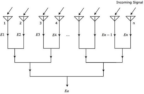
As shown in the figure, all the radiation elements receive the same incoming signal. So, each element produces an equal output voltage of $sin \left ( \omega t \right)$. However, there will be an equal phase difference $\Psi$ between successive elements. Mathematically, it can be written as −
$$\Psi=\frac{2\pi d\sin\theta }{\lambda }\:\:\:\:\:Equation\:1$$
Where,
$\theta$ is the angle at which the incoming signal is incident on each radiation element.
Mathematically, we can write the expressions for output voltages of n radiation elements individually as
$$E_1=\sin\left [ \omega t \right]$$
$$E_2=\sin\left [\omega t+\Psi\right]$$
$$E_3=\sin\left [\omega t+2\Psi\right]$$
$$.$$
$$.$$
$$.$$
$$E_n=\sin\left [\omega t+\left (N-1\right )\Psi\right]$$
Where,
$E_1, E_2, E_3, , E_n$ are the output voltages of first, second, third, , nth radiation elements respectively.
$\omega$ is the angular frequency of the signal.
We will get the overall output voltage $E_a$ of the array by adding the output voltages of each element present in that array, since all those radiation elements are connected in linear array. Mathematically, it can be represented as −
$$E_a=E_1+E_2+E_3+ +E_n \:\:\:Equation\:2$$
Substitute, the values of $E_1, E_2, E_3, , E_n$ in Equation 2.
$$E_a=\sin\left [ \omega t \right]+\sin\left [\omega t+\Psi\right ]+\sin\left [\omega t+2\Psi\right ]+\sin\left [\omega t+\left (n-1\right )\Psi\right]$$
$$\Rightarrow E_a=\sin\left [\omega t+\frac{(n-1)\Psi)}{2}\right ]\frac{\sin\left [\frac{n\Psi}{2}\right]}{\sin\left [\frac{\Psi}{2}\right ]}\:\:\:\:\:Equation\:3$$
In Equation 3, there are two terms. From first term, we can observe that the overall output voltage $E_a$ is a sine wave having an angular frequency $\omega$. But, it is having a phase shift of $\left (n1\right )\Psi/2$. The second term of Equation 3 is an amplitude factor.
The magnitude of Equation 3 will be
$$\left | E_a \right|=\left | \frac{\sin\left [\frac{n\Psi}{2}\right ]}{\sin\left [\frac{\Psi}{2}\right]} \right |\:\:\:\:\:Equation\:4$$
We will get the following equation by substituting Equation 1 in Equation 4.
$$\left | E_a \right|=\left | \frac{\sin\left [\frac{n\pi d\sin\theta}{\lambda}\right]}{\sin\left [\frac{\pi d\sin\theta}{\lambda}\right ]} \right |\:\:\:\:\:Equation\:5$$
Equation 5 is called field intensity pattern. The field intensity pattern will have the values of zeros when the numerator of Equation 5 is zero
$$\sin\left [\frac{n\pi d\sin\theta}{\lambda}\right ]=0$$
$$\Rightarrow \frac{n\pi d\sin\theta}{\lambda}=\pm m\pi$$
$$\Rightarrow nd\sin\theta=\pm m\lambda$$
$$\Rightarrow \sin\theta=\pm \frac{m\lambda}{nd}$$
Where,
$m$ is an integer and it is equal to 1, 2, 3 and so on.
We can find the maximum values of field intensity pattern by using L-Hospital rule when both numerator and denominator of Equation 5 are equal to zero. We can observe that if the denominator of Equation 5 becomes zero, then the numerator of Equation 5 also becomes zero.
Now, let us get the condition for which the denominator of Equation 5 becomes zero.
$$\sin\left [\frac{\pi d\sin\theta}{\lambda}\right ]=0$$
$$\Rightarrow \frac{\pi d\sin\theta}{\lambda}=\pm p\pi$$
$$\Rightarrow d\sin\theta=\pm p\lambda$$
$$\Rightarrow \sin\theta=\pm \frac{p\lambda}{d}$$
Where,
$p$ is an integer and it is equal to 0, 1, 2, 3 and so on.
If we consider $p$ as zero, then we will get the value of $\sin\theta$ as zero. For this case, we will get the maximum value of field intensity pattern corresponding to the main lobe. We will get the maximum values of field intensity pattern corresponding to side lobes, when we consider other values of $p$.
The radiation patterns direction of phased array can be steered by varying the relative phases of the current present at each Antenna. This is the advantage of electronic scanning phased array.
