- Radar Systems - Home
- Radar Systems - Overview
- Radar Systems - Range Equation
- Performance Factors
- Radar Systems - Types of Radars
- Radar Systems - Pulse Radar
- Radar Systems - Doppler Effect
- Radar Systems - CW Radar
- Radar Systems - FMCW Radar
- Radar Systems - MTI Radar
- Delay Line Cancellers
- Radar Systems - Tracking Radar
- Antenna Parameters
- Radar Systems - Radar Antennas
- Matched Filter Receiver
- Radar Systems - Radar Displays
- Radar Systems - Duplexers
- Phased Array Antennas
Radar Systems - Duplexers
In two-way communication, if we are supposed to use the same Antenna for both transmission and reception of the signals, then we require Duplexer. Duplexer is a microwave switch, which connects the Antenna to the transmitter section for transmission of the signal. Therefore, the Radar cannot receive the signal during transmission time.
Similarly, it connects the Antenna to the receiver section for the reception of the signal. The Radar cannot transmit the signal during reception time. In this way, Duplexer isolates both transmitter and receiver sections.
Types of Duplexers
In this section, we will learn about the different types of duplexers. We can classify the Duplexers into the following three types.
- Branch-type Duplexer
- Balanced Duplexer
- Circulator as Duplexer
In our subsequent sections, we will discuss the types of Duplexers in detail.
Branch-type Duplexer
Branch-type Duplexer consists of two switches Transmit-Receive (TR) switch and Anti Transmit-Receive (ATR) switch. The following figure shows the block diagram of Branch-type Duplexer −
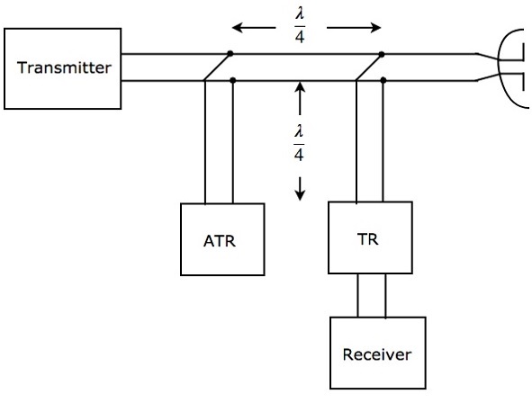
As shown in the figure, the two switches, TR & ATR are placed at a distance of $\lambda/4$ from the transmission line and both the switches are separated by a distance of $\lambda/4$. The working of Branch-type Duplexer is mentioned below.
During transmission, both TR & ATR will look like an open circuit from the transmission line. Therefore, the Antenna will be connected to the transmitter through transmission line.
During reception, ATR will look like a short circuit across the transmission line. Hence, Antenna will be connected to the receiver through transmission line.
The Branch-type Duplexer is suitable only for low cost Radars, since it is having less power handling capability.
Balanced Duplexer
We know that a two-hole Directional Coupler is a 4-port waveguide junction consisting of a primary waveguide and a secondary waveguide. There are two small holes, which will be common to those two waveguides.
The Balanced Duplexer consists of two TR tubes. The configuration of Balanced Duplexer for transmission purpose is shown in the following figure.
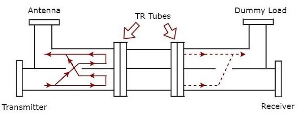
The signal, which is produced by the transmitter has to reach the Antenna for the Antenna to transmit that signal during transmission time. The solid lines with arrow marks shown in the above figure represent how the signal reaches Antenna from transmitter.
The dotted lines with arrow marks shown in the above figure represent the signal, which is leaked from the Dual TR tubes; this will reach only the matched load. So, no signal has been reached to the receiver.
The configuration of Balanced Duplexer for reception purpose is shown in figure given below.
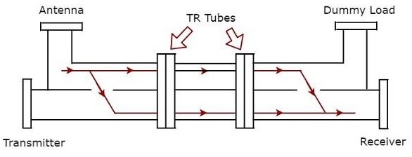
We know that Antenna receives the signal during reception time. The signal which is received by the Antenna has to reach the receiver. The solid lines with arrow marks shown in the above figure represent how the signal is reaching the receiver from Antenna. In this case, Dual TR tubes pass the signal from the first section of waveguide to the next section of waveguide.
The Balanced Duplexer has high power handling capability and high bandwidth when compared to Branch-type Duplexer.
Circulator as Duplexer
We know that the functionality of the circulator is that if we apply an input to a port, then it will be produced at the port, which is adjacent to it in the clockwise direction. There is no output at the remaining ports of the circulator.
So, consider a 4-port circulator and connect the transmitter, Antenna, receiver and matched load to port1, port2, port3 and port4 respectively. Now, let us understand how the 4-port circulator works as Duplexer.
The signal, which is produced by the transmitter has to reach the Antenna for the Antenna will transmit that signal during transmission time. This purpose will be achieved when the transmitter generates a signal at port1.
The signal, which is received by the Antenna has to reach the receiver during reception time. This purpose will be achieved when the Antenna present at port2 receives an external signal.
The following figure shows the block diagram of circulator as Duplexer −
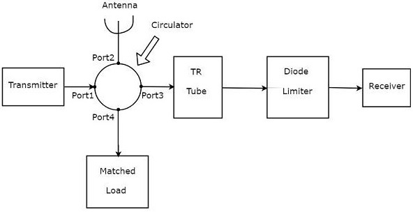
The above figure consists of a 4-port circulator Transmitter, Antenna and the matched load is connected to port1, port2 and port4 of circulator respectively as discussed in the beginning of the section.
The receiver is not directly connected to port3. Instead, the blocks corresponding to the passive TR limiter are placed between port3 of circulator and receiver. The blocks, TR tube & Diode limiter are the blocks corresponding to passive TR limiter.
Actually, the circulator itself acts as Duplexer. It does not require any additional blocks. However, it will not give any kind of protection to the receiver. Hence, the blocks corresponding to passive TR limiter are used in order to provide the protection to the receiver.
