- Radar Systems - Home
- Radar Systems - Overview
- Radar Systems - Range Equation
- Performance Factors
- Radar Systems - Types of Radars
- Radar Systems - Pulse Radar
- Radar Systems - Doppler Effect
- Radar Systems - CW Radar
- Radar Systems - FMCW Radar
- Radar Systems - MTI Radar
- Delay Line Cancellers
- Radar Systems - Tracking Radar
- Antenna Parameters
- Radar Systems - Radar Antennas
- Matched Filter Receiver
- Radar Systems - Radar Displays
- Radar Systems - Duplexers
- Phased Array Antennas
Radar Systems - CW Radar
basic Radar uses the same Antenna for both transmission and reception of signals. We can use this type of Radar, when the target is stationary, i.e., not moving and / or when that Radar can be operated with pulse signal.
The Radar, which operates with continuous signal (wave) for detecting non-stationary targets, is called Continuous Wave Radar or simply CW Radar. This Radar requires two Antennas. Among which, one Antenna is used for transmitting the signal and the other Antenna is used for receiving the signal.
Block Diagram of CW Radar
We know that CW Doppler Radar contains two Antennas − transmitting Antenna and receiving Antenna. Following figure shows the block diagram of CW Radar −
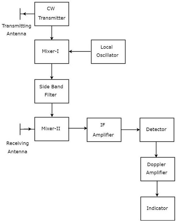
The block diagram of CW Doppler Radar contains a set of blocks and the function of each block is mentioned below.
CW Transmitter − It produces an analog signal having a frequency of $f_o$. The output of CW Transmitter is connected to both transmitting Antenna and Mixer-I.
Local Oscillator − It produces a signal having a frequency of $f_l$. The output of Local Oscillator is connected to Mixer-I.
Mixer-I − Mixer can produce both sum and difference of the frequencies that are applied to it. The signals having frequencies of $f_o$ and $f_l$ are applied to Mixer-I. So, the Mixer-I will produce the output having frequencies $f_o+f_l$ or $f_of_l$.
Side Band Filter − As the name suggests, side band filter allows a particular side band frequencies − either upper side band frequencies or lower side band frequencies. The side band filter shown in the above figure produces only upper side band frequency, i.e., $f_o+f_l$.
Mixer-II − Mixer can produce both sum and difference of the frequencies that are applied to it. The signals having frequencies of $f_o+f_l$ and $f_o\pm f_d$ are applied to Mixer-II. So, the Mixer-II will produce the output having frequencies of 2$f_o+f_l\pm f_d$ or $f_l\pm f_d$.
IF Amplifier − IF amplifier amplifies the Intermediate Frequency (IF) signal. The IF amplifier shown in the figure allows only the Intermediate Frequency, $f_l\pm f_d$ and amplifies it.
Detector − It detects the signal, which is having Doppler frequency, $f_d$.
Doppler Amplifier − As the name suggests, Doppler amplifier amplifies the signal, which is having Doppler frequency, $f_d$.
Indicator − It indicates the information related relative velocity and whether the target is inbound or outbound.
CW Doppler Radars give accurate measurement of relative velocities. Hence, these are used mostly, where the information of velocity is more important than the actual range.
