- Home
- Introduction
- Modulation
- Noise
- Analyzing Signals
- Amplitude Modulation
- Sideband Modulation
- VSB Modulation
- Angle Modulation
- Multiplexing
- FM Radio
- Pulse Modulation
- Analog Pulse Modulation
- Digital Modulation
- Modulation Techniques
- Delta Modulation
- Digital Modulation Techniques
- M-ary Encoding
- Information Theory
- Spread Spectrum Modulation
- Optical Fiber Communications
- Satellite Communications
Principles of Communication - FM Radio
Frequency division multiplexing is used in radio and television receivers. The main use of FM is for radio communications. Let us take a look at the structure of FM transmitter and FM receiver along with their block diagrams and working.
FM Transmitter
FM transmitter is the whole unit which takes the audio signal as an input and delivers FM modulated waves to the antenna as an output to be transmitted. FM transmitter consists of 6 main stages. They are illustrated in the following figure.
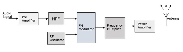
The working of FM transmitter can be explained as follows.
The audio signal from the output of the microphone is given to the pre-amplifier which boosts the level of the modulating signal.
This signal is then passed to the high pass filter, which acts as a pre-emphasis network to filter out the noise and improve the signal to noise ratio.
This signal is further passed to the FM modulator circuit.
The oscillator circuit generates a high frequency carrier, which is given to the modulator along with the modulating signal.
Several stages of frequency multiplier are used to increase the operating frequency. Even then, the power of the signal is not enough to transmit. Hence, a RF power amplifier is used at the end to increase the power of the modulated signal. This FM modulated output is finally passed to the antenna to get transmitted.
Requirements of a Receiver
A radio receiver is used to receive both AM band and FM band signals. The detection of AM is done by the method called as Envelope Detection and the detection of FM is done by the method called as Frequency Discrimination.
Such a radio receiver has the following requirements.
It should be cost effective.
It should receive both AM and FM signals.
The receiver should be able to tune and amplify the desired station.
It should have an ability to reject the unwanted stations.
Demodulation has to be done to all the station signals, whatever the carrier frequency is.
For these requirements to get fulfilled, the tuner circuit and the mixer circuit should be very effective. The procedure of RF mixing is an interesting phenomenon.
RF Mixing
The RF mixing unit develops an Intermediate Frequency (IF) to which any received signal is converted, so as to process the signal effectively.
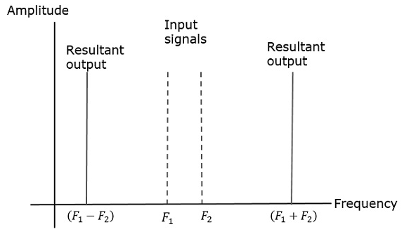
RF Mixer is an important stage in the receiver. Two signals of different frequencies are taken where one signal level affects the level of the other signal, to produce the resultant mixed output. The input signals and the resultant mixer output is illustrated in the following figures.
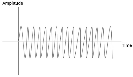
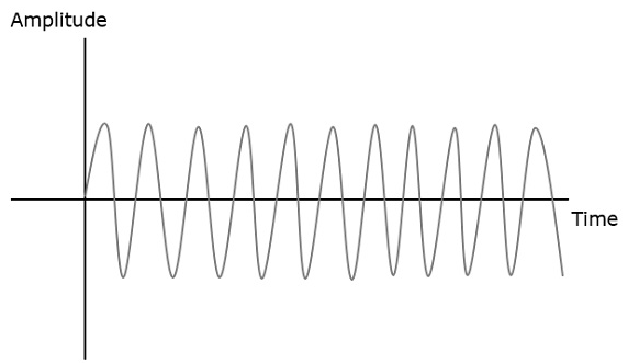
When two signals enter the RF mixer,
The first signal frequency = F1
The second signal frequency = F2
Then, the resultant signal frequencies = (F1 + F2) and (F1 - F2)
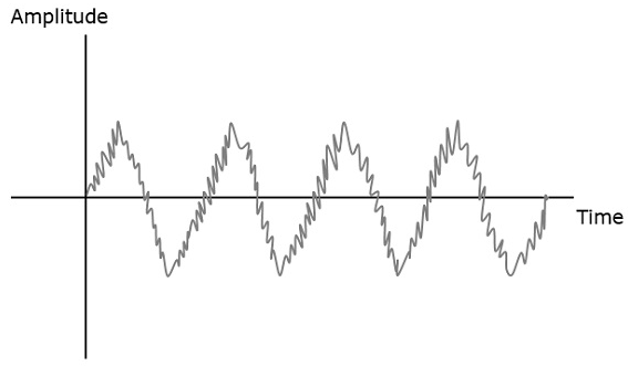
A mixer of two signals of different frequencies are produced at the output.
If this is observed in frequency domain, the pattern looks like the following figure.
The symbol of a RF mixer looks like the following figure.
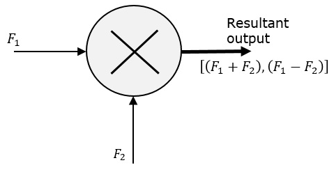
The two signals are mixed to produce a resultant signal, where the effect of one signal, affects the other signal and both produce a different pattern as seen previously.
FM Receiver
The FM receiver is the whole unit which takes the modulated signal as input and produces the original audio signal as an output. Radio amateurs are the initial radio receivers. However, they have drawbacks such as poor sensitivity and selectivity.
Selectivity is the selection of a particular signal while rejecting the others. Sensitivity is the capacity of detecting a RF signal and demodulating it, while at the lowest power level.
To overcome these drawbacks, super heterodyne receiver was invented. This FM receiver consists of 5 main stages. They are as shown in the following figure.
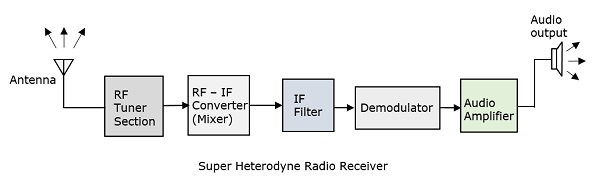
RF Tuner Section
The modulated signal received by the antenna is first passed to the tuner circuit through a transformer. The tuner circuit is nothing but a LC circuit, which is also called as resonant or tank circuit. It selects the frequency, desired by the radio receiver. It also tunes the local oscillator and the RF filter at the same time.
RF Mixer
The signal from the tuner output is given to the RF-IF converter, which acts as a mixer. It has a local oscillator, which produces a constant frequency. The mixing process is done here, having the received signal as one input and the local oscillator frequency as the other input. The resultant output is a mixture of two frequencies [(f1 + f2),(f1 f2)] produced by the mixer, which is called as the Intermediate Frequency (IF).
The production of IF helps in the demodulation of any station signal having any carrier frequency. Hence, all signals are translated to a fixed carrier frequency for adequate selectivity.
IF Filter
Intermediate frequency filter is a bandpass filter, which passes the desired frequency. It eliminates any unwanted higher frequency components present in it as well as the noise. IF filter helps in improving the Signal to Noise Ratio (SNR).
Demodulator
The received modulated signal is now demodulated with the same process used at the transmitter side. The frequency discrimination is generally used for FM detection.
Audio Amplifier
This is the power amplifier stage which is used to amplify the detected audio signal. The processed signal is given strength to be effective. This signal is passed on to the loudspeaker to get the original sound signal.
This super heterodyne receiver is well used because of its advantages such as better SNR, sensitivity and selectivity.
Noise in FM
The presence of noise is a problem in FM as well. Whenever a strong interference signal with closer frequency to the desired signal arrives, the receiver locks that interference signal. Such a phenomenon is called as the Capture effect.
To increase the SNR at higher modulation frequencies, a high pass circuit called preemphasis, is used at the transmitter. Another circuit called de-emphasis, the inverse process of pre-emphasis is used at the receiver, which is a low pass circuit. The preemphasis and de-emphasis circuits are widely used in FM transmitter and receiver to effectively increase the output SNR.
