- Home
- Introduction
- Modulation
- Noise
- Analyzing Signals
- Amplitude Modulation
- Sideband Modulation
- VSB Modulation
- Angle Modulation
- Multiplexing
- FM Radio
- Pulse Modulation
- Analog Pulse Modulation
- Digital Modulation
- Modulation Techniques
- Delta Modulation
- Digital Modulation Techniques
- M-ary Encoding
- Information Theory
- Spread Spectrum Modulation
- Optical Fiber Communications
- Satellite Communications
Analog Pulse Modulation
After the continuous wave modulation, the next division is Pulse modulation. Pulse modulation is further divided into analog and digital modulation. The analog modulation techniques are mainly classified into Pulse Amplitude Modulation, Pulse Duration Modulation/Pulse Width Modulation, and Pulse Position Modulation.
Pulse Amplitude Modulation
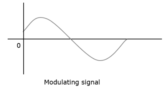
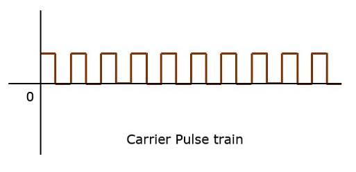
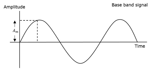
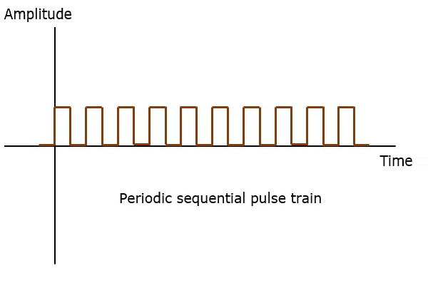
Pulse Amplitude Modulation (PAM) is an analog modulating scheme in which the amplitude of the pulse carrier varies proportional to the instantaneous amplitude of the message signal.
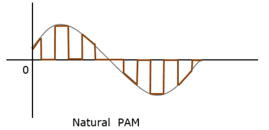
The pulse amplitude modulated signal, will follow the amplitude of the original signal, as the signal traces out the path of the whole wave. In natural PAM, a signal sampled at the Nyquist rate is reconstructed, by passing it through an efficient Low Pass Frequency (LPF) with exact cutoff frequency
The following figures explain the Pulse Amplitude Modulation.
Though the PAM signal is passed through an LPF, it cannot recover the signal without distortion. Hence to avoid this noise, flat-top sampling is done as shown in the following figure.
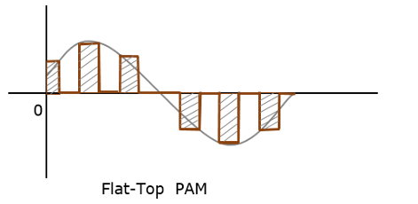
Flat-top sampling is the process in which sampled signal can be represented in pulses for which the amplitude of the signal cannot be changed with respect to the analog signal, to be sampled. The tops of amplitude remain flat. This process simplifies the circuit design.
Pulse Width Modulation
Pulse Width Modulation (PWM) or Pulse Duration Modulation (PDM) or Pulse Time Modulation (PTM) is an analog modulating scheme in which the duration or width or time of the pulse carrier varies proportional to the instantaneous amplitude of the message signal.
The width of the pulse varies in this method, but the amplitude of the signal remains constant. Amplitude limiters are used to make the amplitude of the signal constant. These circuits clip off the amplitude, to a desired level and hence the noise is limited.
The following figures explain the types of Pulse Width Modulations.
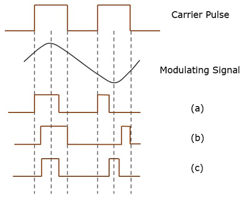
There are three variations of PWM. They are −
The leading edge of the pulse being constant, the trailing edge varies according to the message signal.
The trailing edge of the pulse being constant, the leading edge varies according to the message signal.
The center of the pulse being constant, the leading edge and the trailing edge varies according to the message signal.
These three types are shown in the above given figure, with timing slots.
Pulse Position Modulation
Pulse Position Modulation (PPM) is an analog modulating scheme in which the amplitude and width of the pulses are kept constant, while the position of each pulse, with reference to the position of a reference pulse varies according to the instantaneous sampled value of the message signal.
The transmitter has to send synchronizing pulses (or simply sync pulses) to keep the transmitter and receiver in synchronism. These sync pulses help maintain the position of the pulses. The following figures explain the Pulse Position Modulation.
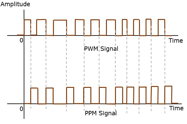
Pulse position modulation is done in accordance with the pulse width modulated signal. Each trailing of the pulse width modulated signal becomes the starting point for pulses in PPM signal. Hence, the position of these pulses is proportional to the width of the PWM pulses.
Advantage
As the amplitude and width are constant, the power handled is also constant.
Disadvantage
The synchronization between transmitter and receiver is a must.
Comparison between PAM, PWM, and PPM
The comparison between the above modulation processes is presented in a single table.
| PAM | PWM | PPM |
|---|---|---|
| Amplitude is varied | Width is varied | Position is varied |
| Bandwidth depends on the width of the pulse | Bandwidth depends on the rise time of the pulse | Bandwidth depends on the rise time of the pulse |
| Instantaneous transmitter power varies with the amplitude of the pulses | Instantaneous transmitter power varies with the amplitude and width of the pulses | Instantaneous transmitter power remains constant with the width of the pulses |
| System complexity is high | System complexity is low | System complexity is low |
| Noise interference is high | Noise interference is low | Noise interference is low |
| It is similar to amplitude modulation | It is similar to frequency modulation | It is similar to phase modulation |
