
Article Categories
- All Categories
-
 Data Structure
-
 Networking
-
 RDBMS
RDBMS
-
 Operating System
-
 Java
Java
-
 MS Excel
-
 iOS
iOS
-
 HTML
HTML
-
 CSS
CSS
-
 Android
-
 Python
-
 C Programming
-
 C++
C++
-
 C#
C#
-
 MongoDB
-
 MySQL
MySQL
-
 Javascript
-
 PHP
PHP
-
 Economics & Finance
Loaded and Unloaded Voltage Dividers
A voltage divider or potential divider is a series circuit that is used to provide more than one reduced voltages from a single source of voltage.
Consider a circuit of voltage divider as shown below, in which two reduced voltages V1 and V2 are obtained from a single input voltage source of V volts. Since no load is connected to circuit, it is called unloaded voltage divider.
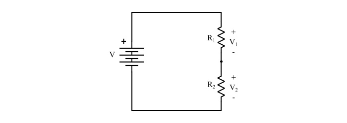
Refer the circuit of unloaded voltage divider,
$$\mathrm{Circuit\:Current,I= \frac{V}{R_{1}+{R_{2}}}=\frac{V}{R_{eq}}}\:\:\:… (1)$$
Where,Req=R1 + R2= Total resistance of voltage divider
Therefore,
$$\mathrm{V_{1}=IR_{1}=\frac{V}{R_{eq}}×R_{1}=V\frac{R_{1}}{R_{eq}}}\:\:\:… (2)$$
$$\mathrm{V_{2}=IR_{2}=\frac{V}{R_{eq}}×R_{2}=V\frac{R_{2}}{R_{eq}}}\:\:\:… (3)$$
Hence, equation (2) and (3) shows that, the voltage drop across any resistor in an unloaded voltage divider is equal to the total source voltage multiplied by the ratio of that resistance value to the total resistance.
Loaded Voltage Divider
When a load resistance RL is connected across the output terminals of the voltage divider, the voltage divider is said to be loaded.
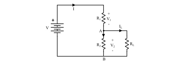
Due to this RL, the output voltage (V2 in this case) is reduced by an amount depending on the value of RL. It is because the load resistance RL is in parallel with R2 and reduces the effective resistance between the load terminals (here, A and B), as a result the output voltage is reduced. The loading of voltage divider has following effects −
The output voltage decreases depending upon the value of load resistor RL.
After connected the load resistor, the voltage divider circuit turned into a series-parallel circuit. Therefore, the total resistance of the circuit is reduced.
The circuit current increases because the total resistance of the circuit is decreased.
Numerical Example
In the voltage divider circuit shown below, determine the following −
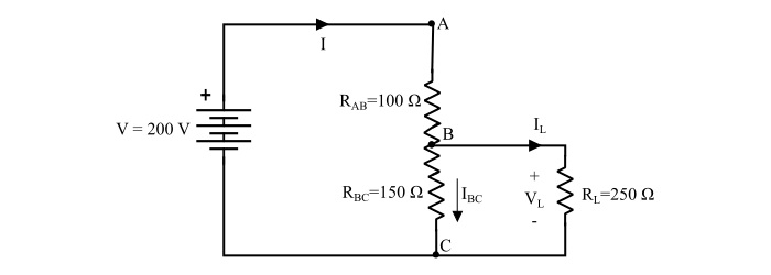
- Total current drawn from the supply
- Voltage across the load resistor
- The current flowing through RL
- The current in the tapped portion.
Solution
The equivalent resistance of the given voltage divider is,
$$\mathrm{R_{BC\:eq}=(R_{BC}\:||\:R_{L})=\frac{150 × 250}{150 + 250}= 93.75 Ω}$$
$$\mathrm{∴R_{eq}=R_{AB}\:+\:R_{BC\:eq}= 100 + 93.75 = 193.75 Ω}$$
Total current drawn from the source
$$\mathrm{I=\frac{V}{R_{eq}}=\frac{200}{193.75}= 1.032 A}$$
Voltage across load resistor
$$\mathrm{V_{L}=V×\frac{R_{BC\:eq}}{R_{eq}}= 200 ×\frac{93.75}{193.75}= 96.77 Ω}$$
The current flowing through RL
$$\mathrm{I_{L}=\frac{V_{L}}{R_{L}}=\frac{96.77}{250}= 0.387 A}$$
Current in the tapped portion
$$\mathrm{I_{Bc}=I-I_{L}=1.032 − 0.387 = 0.645 A}$$

9K+ Views
