
Article Categories
- All Categories
-
 Data Structure
-
 Networking
-
 RDBMS
RDBMS
-
 Operating System
-
 Java
Java
-
 MS Excel
-
 iOS
iOS
-
 HTML
HTML
-
 CSS
CSS
-
 Android
-
 Python
-
 C Programming
-
 C++
C++
-
 C#
C#
-
 MongoDB
-
 MySQL
MySQL
-
 Javascript
-
 PHP
PHP
-
 Economics & Finance
Voltage Multipliers – Circuit, Operation, Types, and Applications
An electronic circuit consisting of diodes and capacitors and converts an AC electrical signal from a lower voltage value to a higher DC voltage value is referred to as a voltage multiplier. Voltage multipliers are used in several electronic appliances to generate a voltage signal of few volts to millions of volts.
In this article, we will discuss the definition, circuit, types, operation, and applications of the voltage multiplier.
What is a Voltage Multiplier?
A voltage multiplier is an electronic circuit consisting of capacitors and diodes and is used to multiply or rise the voltage level of an AC signal. The voltage multiplier receives an AC voltage of lower value, converts it into a DC voltage and increases its voltage level. Therefore, a voltage multiplier circuit performs both rectification and multiplication of voltage. Here, the rectification operation is performed by diodes and the increase in voltage is achieved by the capacitors.
Circuit of Voltage Multiplier
The circuit of a simple voltage multiplier is shown in Figure-1.
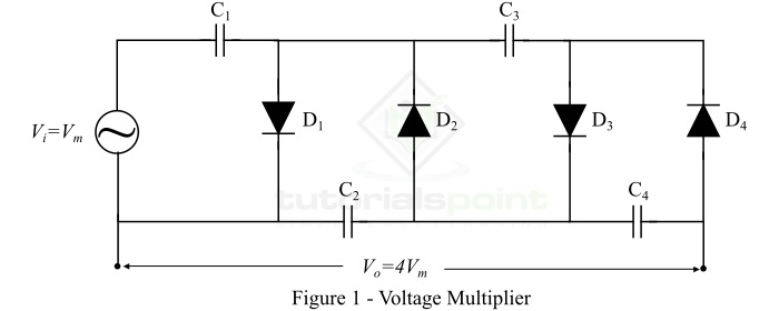
It is clear that a voltage multiplier is simply a combination of diodes and capacitors. The low voltage AC signal is input to the circuit from the power source (transformer in this case). This AC voltage is converted into DC voltage by diodes and increased by capacitors. In this way, the voltage multiplier gives a DC voltage of high value. This output DC voltage can be several times higher than the input voltage, hence, the load circuit must have high impedance.
Operation of Voltage Multiplier
Now, let us understand the operation of the voltage multiplier shown in Figure-1. Let the maximum value of the AC input voltage is +Vm. Then, the operation of the voltage multiplier is as follows ?
Step 1 ? With Negative Peak of Input Voltage (-Vm) ? The capacitor C1 is charged through the diode D1 to a voltage equal to Vm volts.
Step 2 ? With Positive Peak of Input Voltage (+Vm) ? In this step, the voltage of the capacitor C1 adds with that of the input source. Thus, charging the capacitor C2 to 2Vm volts through the diode D2.
Step 3 ? With Second Negative Peak (-Vm) ? The voltage of the capacitor C1 has dropped to 0 volts, hence allowing the capacitor C3 to be charged through the diode D3 to the voltage of 2Vm volts.
Step 4 ? With Second Positive Peak (+Vm) ? In this step, the voltage of the capacitor C2 increases to 2Vm volts like in the step-2. This is also charging the capacitor C4 to the voltage 2Vm. Hence, the total output voltage is the sum of voltage under the capacitors C2 and C4, i.e. 4Vm.
Note ? In actual practice, more cycles are required for C4 to reach the full output voltage
Types of Voltage Multipliers
Based on the ratio of the input voltage to the output voltage, the voltage multipliers are classified into the following three types ?
- Voltage Doubler
- Voltage Tripler
- Voltage Quadrupler
Let us discuss each of these three types of voltage multipliers one by one.
Voltage Doubler
As the name implies, a voltage doubler is a type of voltage multiplier that doubles the input voltage. The circuit of a voltage doubler is shown in Figure-2.
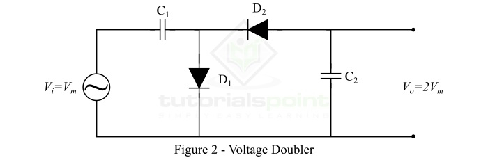
It consists of two capacitors and two diodes. Thus, the voltage doubler circuit is a two-stage voltage multiplier. A typical example of a voltage doubler is found in the switch mode power supply which contains a SPDT (single pole double throw) switch to select either 120 V or 240 V power supply.
Voltage Tripler
A voltage tripler, as its name suggests, is a three stage voltage multiplier. The voltage tripler is one of the most popular type of voltage multipliers. The voltage tripler uses three capacitors and three diodes, connected, as shown in Figure-3, to produce an output DC voltage approximately equal to the three times of the maximum value of the input AC voltage.
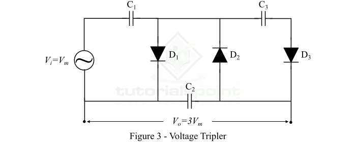
In actual practice, the output DC voltage of a voltage tripler circuit is always below the three times of the maximum input voltage because of their high impedance and voltage loses in different stages due to partial discharges.
Some common applications of voltage tripler are in CRT color TVs, photo copier machines, laser printers, electroshock weapons, etc.
Voltage Quadrupler
A voltage quadrupler is a voltage multiplier circuit which gives an output DC voltage that is approximately equal to the four times of the maximum input voltage. The voltage quadrupler is a simply a stacked combination of two voltage doubler circuits as shown in Figure-4.

Applications of Voltage Multipliers
The voltage multipliers are used to produce a DC voltage of few volts for electronic circuits to millions of volts for applications like high energy physics experiments. Some common applications of voltage multipliers are as follows ?
- Cathode ray tubes used in TV receivers, computer monitors, oscilloscopes, etc.
- Laser printers and photo copier machines
- X-ray machines
- Photo multiplier tubes
- Travelling wave tubes
- Ion pumps
- Bug zappers
- Voltage multiplier is also used in Cockcroft-Walton Generator, etc.
- In automobile manufacturing industries, the high voltage multipliers are used in spray painting machine
Conclusion
A voltage multiplier is an electronic circuit consisting of diodes and capacitors that can convert an AC voltage from a lower value to a DC voltage of a higher value.
Based on the multiplication of voltage, the voltage multiplier circuits are classified into three main types namely, voltage doubler (doubles the peak voltage), voltage tripler (triples the peak voltage), and voltage quadrupler (increases the voltage four time of the peak value).
Voltage multipliers are extensively used in several low current and high voltage applications such as CRT TV receivers, CRT monitors, oscilloscopes, laser printers, photo copier machines, etc.

32K+ Views
