
Article Categories
- All Categories
-
 Data Structure
-
 Networking
-
 RDBMS
RDBMS
-
 Operating System
-
 Java
Java
-
 MS Excel
-
 iOS
iOS
-
 HTML
HTML
-
 CSS
CSS
-
 Android
-
 Python
-
 C Programming
-
 C++
C++
-
 C#
C#
-
 MongoDB
-
 MySQL
MySQL
-
 Javascript
-
 PHP
PHP
-
 Economics & Finance
Inverting and Non-Inverting Operational Amplifiers
An operational amplifier is a three-terminal device consisting of two high impedance input terminals, one is called the inverting input denoted by a negative sign and the other is the non-inverting input denoted with a positive sign. The third terminal is the output of the Op-Amp.
Inverting Operational Amplifier
In the inverting operational amplifier circuit, the signal is applied at the inverting input and the non-inverting input is connected to the ground. In this type of amplifier, the output is 180? out of phase to the input, i.e. when positive signal is applied to circuit, the output of the circuit will be negative. By assuming the Op-Amp is ideal, then the concept of virtual short can be applied at the input terminals of the Op-Amp. So that voltage at the inverting terminal is equal to the voltage at non-inverting terminal.
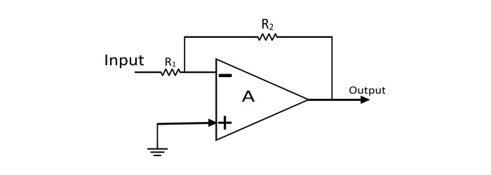
Applying KCL at inverting node of Op-Amp
$$\mathrm{\frac{0-V_{in}}{R_{1}}+\frac{0-V_{out}}{R_{2}}=0}$$
$$\mathrm{Voltage\:Gain(A_{v})=\frac{V_{out}}{V_{in}}=-\frac{R_{2}}{R_{1}}}$$
Non-Inverting Operational Amplifier
When the signal is applied at the non-inverting input, the resulting circuit is known as Non-Inverting Op-Amp. In this amplifier the output is exactly in phase with the input i.e. when a positive voltage is applied to the circuit, the output will also be positive. By assuming the Op-Amp is ideal, then concept of virtual short can be applied i.e. the voltage at the inverting and non-inverting terminal is equal.
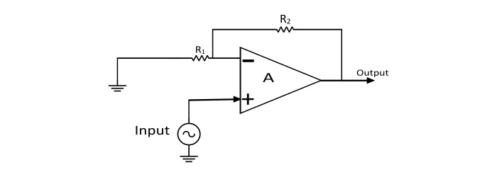
Applying KCL at the inverting node
$$\mathrm{\frac{V_{in}-V_{out}}{R_{2}}+\frac{V_{0}-0}{R_{1}}=0}$$
$$\mathrm{Voltage\:Gain(A_{v})=\frac{V_{out}}{V_{in}}=1+\frac{R_{2}}{R_{1}}}$$
Difference between Inverting and Non-Inverting Op-Amps
| Inverting Op-Amp | Non-Inverting Op-Amp |
|---|---|
| The type of feedback used is voltage shunt. | The type of feedback used is voltage series. |
| The input and output voltages of this amplifier are 180? out of phase. | The input and output voltages are in phase. |
| $$\mathrm{Voltage\:Gain(A_{v})=\frac{V_{out}}{V_{in}}=-\frac{R_{2}}{R_{1}}}$$ |
$$\mathrm{Voltage\:Gain(A_{v})=\frac{V_{out}}{V_{in}}=1+\frac{R_{2}}{R_{1}}}$$ |
| The input impedance is R1. | The input impedance is very high. |

96K+ Views
