
Article Categories
- All Categories
-
 Data Structure
-
 Networking
-
 RDBMS
RDBMS
-
 Operating System
-
 Java
Java
-
 MS Excel
-
 iOS
iOS
-
 HTML
HTML
-
 CSS
CSS
-
 Android
-
 Python
-
 C Programming
-
 C++
C++
-
 C#
C#
-
 MongoDB
-
 MySQL
MySQL
-
 Javascript
-
 PHP
PHP
-
 Economics & Finance
Selected Reading
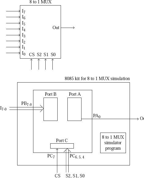
Simulation of 8 to 1 multiplexer
We shall write a program in assembly language just for the simulation of a multiplexer 8 to 1 which is used by the logic controller interface.
The pins of the 8 to 1 multiplexer to be simulated are assumed to be as shown in the fig.
For this multiplexer simulation, 8255 ports as indicated in the following provide the inputs and outputs.
- Port B used as I7-0 inputs;
- Pin 7 of Port C used as chip select;
- Pins 6-4 of Port C used as select inputs;
- Pin 0 of Port A used as output of multiplexer.
Sample Code
FILE NAME Prog_MUX.ASM
ORG C100H
TABLE DB 01H, 02H, 04H, 08H, 10H, 20H, 40H, 80H

ORG C000H
PA EQU D8H
PB EQU D9H
PC EQU DAH
CTRL EQU DBH

MVI A, 10001010B
OUT CTRL ; Configure 8255 ports

LOOP: IN PC
RLC
JNC LOOP ; Wait in the loop till chip is enabled

RLC
RLC
RLC

ANI 07H ; Now LS 3 bits of A will have select inputs

LXI H, TABLE
ADD L
MOV L, A ; Point HL to proper row of look up table

IN PB
ANA M ; AND Port B with a value from look up table
JZ SKIP

MVI A, 01H
SKIP: OUT PA ; Send out the value of selected input
JMP LOOP

Updated on: 2019-07-30T22:30:25+05:30
906 Views

Advertisements