
Article Categories
- All Categories
-
 Data Structure
-
 Networking
-
 RDBMS
RDBMS
-
 Operating System
-
 Java
Java
-
 MS Excel
-
 iOS
iOS
-
 HTML
HTML
-
 CSS
CSS
-
 Android
-
 Python
-
 C Programming
-
 C++
C++
-
 C#
C#
-
 MongoDB
-
 MySQL
MySQL
-
 Javascript
-
 PHP
PHP
Explain the cross product method process in DFA
The cross product method process in the deterministic finite automata (DFA) is explained below −
Let a's DFA diagram has m number of states and b's DFA diagram has n number of states the cross product m x n will have mxn states.
Languages represented by even number of ‘a’ and even number of ‘b’ are given below −
L1 = {ε, baa, aa, aba, aab, aaaa, ... }
L2 = {ε bb, abb, bab, bba, ...}
After cross product we will find the DFA as mentioned below −
As, L = {ab, aab, abb, aaab, ...}
Example
Let’s taken two DFAs
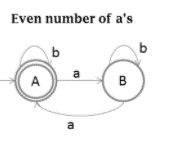
- Even number of a's
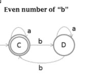
- Even number of b's
The DFA for even number of a’s is as follows −
The DFA for even number of b’s is as follows −
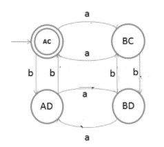
Cross product of two languages is as follows −
{A, B} X {C, D} = {AC, AD, BC, BD}
The state transition diagram for the cross product of two languages is given below −
Example
Determine the transition for each state (AC, AD, BC, BD) and for each input (a,b).
Explanation
Follow the steps given below to find out the transition for each state and for each input.
- Step 1
State AC and input a
a's DFA diagram − A → a → B
b's DFA diagram − C → a → C
Result − AC→ a → BC
- Step 2
State AC and input b
a's DFA diagram − A → b → A
b's DFA diagram − C → b → D
Result − AC→ b → AD
- Step 3
State BC and input a
a's DFA diagram − B → a → A
b's DFA diagram − C → a → C
Result − BC→ a → AC
- Step 4
State BC and input b
a's DFA diagram − B → b → B
b's DFA diagram − C → b → D
Result − BC→ b → BD
- Step 5
State BD and input a
a's DFA diagram − B → a → A
b's DFA diagram − D → a → D
Result − BD→ a → AD
- Step 6
State BD and input b
a's DFA diagram − B → b → B
b's DFA diagram − D → b → C
Result − BD→ b → BC
- Step 7
State AD and input a
a's DFA diagram − A → a → B
b's DFA diagram − D → a → D
Result − AD→ a → BD
- Step 8
State AD and input b
a's DFA diagram − A → b → A
b's DFA diagram − D → b → C
Result − AD→ b → AC

2K+ Views
